ME12002
HYDRAULIC SYSTEM
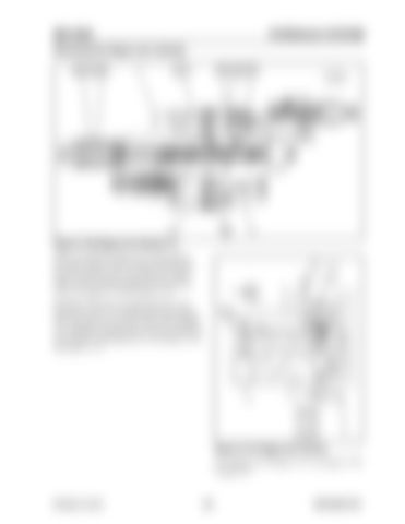
Retracting the Dipper Arm Cylinder
Figure 3-130 Dipper Arm Section (1) While extending the dipper arm, pilot pressure from pilot control valve (31) flows through pilot line (29), pilot line (24), and shifts arm 1 spool (302) to the left against spring (322) and spring (328). See Figure 3-130 and Figure 3-131. Hydraulic fluid from rear pump (28) flows into load check valve (511) and through center bypass (10), into path (15), arm lock valve (516) and path (14). Hydraulic fluid then flows into the rod side of arm cylinder (1) through line (3). See Figure 3-130 and Figure 3-131.
Figure 3-131 Dipper Arm Control For a larger view of Figure 3-131, see Figure 3-128 on page 128.
Printed in U.S.A
129
909768/BP1207


