HYDRAULIC SYSTEM
ME12002
Regeneration Circuit
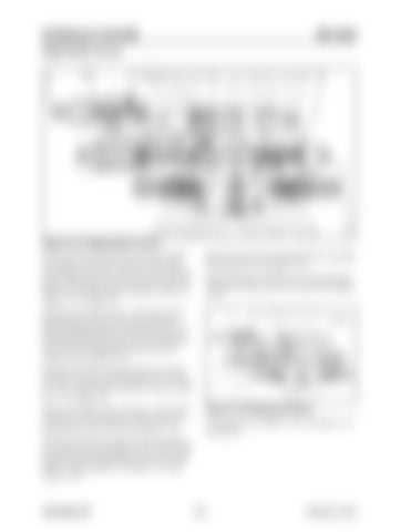
Figure 3-121 Regeneration Circuit Return flow from the head side of boom cylinder (1) separates at line (44). A portion of this flow opens check valve (14), check valve (47), and then passes through path (34) in boom spool (303). See Figure 3-121, and for boom cylinder (1) only, see Figure 3-111 on page 119.
Path (43) shuts-off, intercepting the flow from path (44) to path (34). See Figure 3-121. Spring (49) shuts-off check valve (14) and spring (38) presses check valve (47) to the left. See Figure 3-121.
Because boom spool (303) is in the left position, path (48) pressure flows into return path (15), relieving spring chamber (39) pressure. Path (34) hydraulic fluid forces check valve (47) and check valve (14) to the right against spring (38) and spring (49). See Figure 3-121. Hydraulic fluid flows through path (36) and port (4) into the rod side of boom cylinder (1). See Figure 3-121, and for boom cylinder (1) only, see Figure 3-111 on page 119. While lowering the boom, the boom 1 spool (303) regenerative circuit function transfers flow from the head side to the rod side. See Figure 3-121.
Figure 3-122 Raising the Boom For a larger view of Figure 3-122, see Figure 3-117 on page 122.
When the control lever returns to the neutral position, pilot pressure through port (23) is cut-off and spring (322) and spring (328) returns boom spool (303) to neutral position. See Figure 3-121 and Figure 3-122.
909768/BP1207
124
Printed in U.S.A


