HYDRAULIC SYSTEM
ME12002
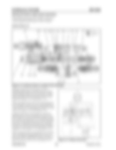
Raising the Boom (high speed operation) During high speed operation, the pilot control lever is fully operated and the spool is fully switched. Section Boom (1)
Figure 3-113 Section Boom (1) (spool fully switched) Hydraulic fluid from front pump (27) flows through parallel path (17) and into boom 1 spool (303). Hydraulic fluid from rear pump (28) flows through parallel path (18) and into boom 2 spool (306). See Figure 3-114 and Figure 3-115. While raising the boom, port (5) senses pilot pressure from pilot control valve (25) and shifts boom 1 spool (303) to the right against springs (322) and (328). See Figure 3-113 and Figure 3-114. Hydraulic fluid from front pump (27) and from parallel path (17) flows through load check valve (511), path (39) and path (35). The hydraulic fluid then forces open boom lock valve (516), and flows into port (3). Hydraulic fluid then flows through line (6) (not shown) and into the head side of boom cylinder (1). See Figure 3-113 and Figure 3-114. While raising the boom, the path above boom lock valve (516) leads through path (20), sleeve (37) and spool (202) to path (38). Pressure in path (33) opens boom lock valve (516). See Figure 3-113. 909768/BP1207
Figure 3-114 Boom Structure 120
Printed in U.S.A


