Mustang Compact Excavator ME12002 Service Manual_909768 - PDF DOWNLOAD

Page 124

HYDRAULIC SYSTEM •

If both travel spools (301R) and (301L) operate simultaneously or if only travel right spool (301R) operates, hydraulic fluid flows into path (15) (not shown), then through path (16) (not shown), shuttle valve (11) (not shown), and into pilot path (12). See Figure 3-101 and Figure 3-104 on page 115.

If only travel left spool (301L) operates, hydraulic fluid flows into path (9), then through path (5), path (6), shuttle valve (11) (not shown), and into pilot path (12). See Figure 3-101, Figure 3-102, and Figure 3-104 on page 115.

If path (13) pressure is less than main relief valve (601) set pressure, valve washer (24) and seat (25) are shut-off and hydraulic fluid in path (13) cannot flow into return path (14). See Figure 3-101 and Figure 3-103 on page 115. While traveling, path (12) pilot pressure flows through path (25) and into the left end of piston (17). Piston (17) moves to the right and presses against spring (39), increasing the spring force pressure. When path (13) hydraulic fluid is pressurized close to the high pressure setting, valve washer (24) opens against spring (39). Hydraulic fluid in chamber (33) then flows through path (32) and into return path (14), with its pressure decreased. See Figure 3-101 and Figure 3-103 on page 115. Hydraulic fluid pressure in path (13) moves piston (37) to the left and presses against the right end of plug (40). Simultaneously, path (13) hydraulic fluid flows into path (30), with its pressure decreased by opening (31). Hydraulic fluid pressure in spring chamber (35) decreases because fluid flows through path (36) and into path (30). The pressure from path (13) presses plunger (38) to the left against spring (34). Plunger (38) opens and path (13) hydraulic fluid flows into return path (14), maintaining the high pressure setting. Adjustment plug (26) adjusts the high pressure setting. See Figure 3-101 on page 115.

909768/BP1207

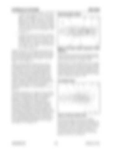
ME12002 Operating Main Relief

Figure 3-105 Main Relief Operation While Working While traveling, the force pressing against spring (39) decreases, and the force pressing against valve washer (24) decreases. See Figure 3-105. When path (13) is pressurized close to the working pressure setting, valve washer (24) opens. Plunger (38) opens and path (13) hydraulic fluid flows into return path (14) to maintain the working pressure setting. Adjustment screw (25) adjusts the working pressure setting. See Figure 3-105.

Port Relief Valve

Figure 3-106 Port Relief Valve Port relief and make-up valves are installed between the cylinders and spools of working components (boom, dipper arm, and bucket). When an external force acts on a cylinder rod, and its spool is in neutral, pressure within the cylinder can become excessive. Port relief valve restricts this pressure to the valve set pressure.

116

Printed in U.S.A


Turn static files into dynamic content formats.

Create a flipbook

Articles inside

ME12002TROUBLESHOOTING

1min
page 311

ME12002TROUBLESHOOTING

1min
pages 309-310

JOHNDEEREENGINE4045TF270(SNAC02633ANDUP)ME12002

43min
pages 230-235, 237-298

JOHNDEEREENGINE4045TF270(SNAC02633ANDUP)ME12002

3min
pages 226-229

JOHNDEEREENGINE4045TF270(SNAC02633ANDUP)ME12002

5min
pages 222-225

JOHNDEEREENGINE4045TF270(SNAC02633ANDUP)ME12002

4min
pages 216-221

HYDRAULICSYSTEMME12002

2min
pages 208, 211-215

ME12002HYDRAULICSYSTEM

1min
pages 205-207

ME12002HYDRAULICSYSTEM

1min
pages 203-204

HYDRAULICSYSTEMME12002

1min
page 202

ME12002HYDRAULICSYSTEM

1min
page 201

ME12002HYDRAULICSYSTEM

1min
pages 199-200

HYDRAULICSYSTEMME12002

1min
pages 188-190

ME12002HYDRAULICSYSTEM

1min
page 187

HYDRAULICSYSTEMME12002

1min
page 186

ME12002HYDRAULICSYSTEM

1min
page 185

ME12002HYDRAULICSYSTEM

3min
pages 179-184

HYDRAULICSYSTEMME12002

1min
page 174

HYDRAULICSYSTEMME12002

2min
pages 168-173

ME12002HYDRAULICSYSTEM

3min
pages 161-167

HYDRAULICSYSTEMME12002

1min
page 160

ME12002HYDRAULICSYSTEM

1min
page 159

ME12002HYDRAULICSYSTEM

1min
pages 155-156

ME12002HYDRAULICSYSTEM

1min
pages 153-154

HYDRAULICSYSTEMME12002

1min
page 152

ME12002HYDRAULICSYSTEM StraightTravelSpool(noadditionalactuation)

1min
page 151

ME12002HYDRAULICSYSTEM

1min
pages 149-150

HYDRAULICSYSTEMME12002

3min
pages 140-146

ME12002HYDRAULICSYSTEM

1min
page 139

ME12002HYDRAULICSYSTEM

1min
pages 137-138

RegenerationCircuit

3min
pages 132-136

HYDRAULICSYSTEMME12002

3min
pages 128-131

ME12002HYDRAULICSYSTEM

1min
page 125

OperatingMainRelief

1min
page 124

HYDRAULICSYSTEMME12002

1min
page 124

ME12002HYDRAULICSYSTEM OperatingPilotPressure

1min
page 123

FineMetering

1min
page 117

HYDRAULICSYSTEMME12002 ValveStructure

1min
page 116

HYDRAULICSYSTEMME12002

1min
pages 104-109

HYDRAULICSYSTEMME12002

1min
pages 102-103

ME12002HYDRAULICSYSTEM

1min
page 101

HYDRAULICSYSTEMME12002

1min
page 100

ME12002HYDRAULICSYSTEM

1min
page 99

ME12002HYDRAULICSYSTEM

1min
page 97

ME12002HYDRAULICSYSTEM

1min
page 95

HYDRAULICSYSTEMME12002

1min
page 94

HYDRAULICSYSTEMME12002

1min
page 92

HYDRAULICSYSTEMME12002

5min
pages 82-91

HYDRAULICSYSTEMME12002

2min
pages 78-81

ME12002HYDRAULICSYSTEM

1min
page 77

HYDRAULICSYSTEMME12002

1min
page 76

HYDRAULICSYSTEMME12002

1min
page 74

HYDRAULICSYSTEMME12002

1min
pages 72-73

MAINTENANCEME12002

4min
pages 54-57, 59-64

MAINTENANCEME12002

1min
pages 52-53

MAINTENANCEME12002

2min
pages 48-51

MAINTENANCEME12002 HydraulicPumpPartInspection

2min
pages 42-47

ME12002TECHNICALDATA

1min
pages 13-14
Issuu converts static files into: digital portfolios, online yearbooks, online catalogs, digital photo albums and more. Sign up and create your flipbook.
Mustang Compact Excavator ME12002 Service Manual_909768 - PDF DOWNLOAD by www.heydownloads.com - Issuu