ME12002
HYDRAULIC SYSTEM
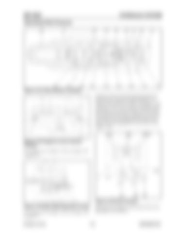
Operating Pilot Pressure
Figure 3-101 Pilot Pressure Traveling Hydraulic fluid traveling through pilot path (12) pilot pressure connects to piston chamber (17), inside of main relief valve (601). See Figure 3-101 and Figure 3-103. This connection shifts the piston and increases the pressure setting. The flow from pilot pump (21) (not shown) separates at line (10), one portion flows through path (9) and the other portion flows through path (15) (not shown). See Figure 3-102.
Figure 3-102 Negative Control System Function For a larger view of Figure 3-102, see Figure 3-87 on page 107.
Figure 3-104 Drive Function Figure 3-103 Main Relief Operation (Travel)
Both path (9) and path (15) (not shown) flow into pilot path (12) as follows:
For a larger view of Figure 3-103, see Figure 3-98 on page 113. Printed in U.S.A
115
909768/BP1207


