HYDRAULIC SYSTEM
ME12002
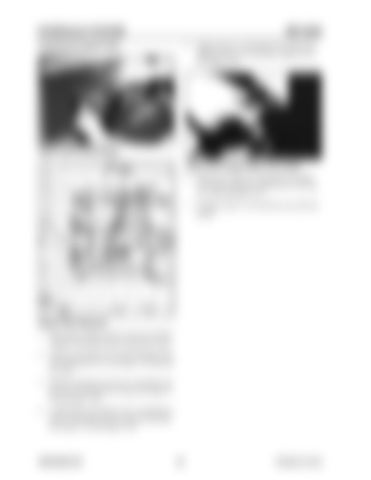
Installing the Swash Plate
5. Apply grease to swash plate (212) and to the sliding sections of swash plate support (251). See Figure 3-60.
Figure 3-59 Pump Casing Figure 3-61 Swash Plate, Drive Shaft 6. Install drive shaft (111) through swash plate (212) and swash plate support (251). See Figure 3-60 and Figure 3-61. 7. Complete steps 1-6 for both the rear and front pumps.
Figure 3-60 Tilting Pin 1. Place pump casing onto the work area with the regulator-mounting surface facing downward. 2. Install swash plate (212) and tilt bushing (214) onto tilting pin (531). See Figure 3-59 and Figure 3-60. 3. Install swash plate (212) onto swash plate support (251) and install the O-ring. See Figure 359 and Figure 3-60. 4. Confirm that swash plate (212) is installed correctly. Check that it can be removed smoothly. See Figure 3-59 and Figure 3-60.
909768/BP1207
92
Printed in U.S.A


