Toyota Orderpicker Model 7BPUE 15 Service Manual
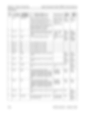
Section 9. Theory of Operation Pinout Matrix
relationship between CH A & B to determine direction and speed. JPS1-19
JPS1-12
12 V
GND
supply.
+10.8 - 13Vdc w/key switch closed
Steer Controller Card
Steer Feedback Encoder
B- for the steer feedback encoder.
<O.SVdc wrt TP4
Steer Controller Card
Steer Feedback Encoder
Positive supply for the steer motor encoder from the wire guidance manager power
(B-1 JPS1-13
NC
Not connected to any circuitry.
JPS1-19
NC
Not connected to any circuitry.
JPS1-2
NC
Not connected to any circuitry.
JPS1-20
NC
Not connected to any circuitry.
JPS4-1
TERM
Terminating resistor for the communication system.
Steer Controller Card
Steer Controller Card
JPS4-4
RES
Terminating resistor for the communication system.
Steer Controller Card
Steer Controller Card
JPS4-3
DGND
B- supplied to the steer controller from the STM.
<O.SVdc wrt TP4
STM
Steer Controller Card
(B-1
JPS4-6
BUS+
The wire that carries the positive component of the digital communications between the STM and the Wire Guidance manager. N o usable information can be gained by measuring the voltage on this wire.
N o useful voltages are measurable
STM/ WGM
STM/ WGM
JPS4-5
BUS-
The wire that carries the negative component of the digital communications between the STM and the Wire Guidance manager. N o usable information can be gained by measuring the voltage on this wire.
N o useful voltages are measurable
STM/ WGM
STM/ WGM
JPS2-24
B-
B- supplied to the steer controller from the STM.
<O.SVdc wrt TP4
STM
Steer Controller Card
B+ supply for the power supply on the steer controller card.
B+ EPO closed OV EPO Open
STM
Steer Controller Card
JPS2-11
B+ESTOP
(B-1
00700-CL222-05, 1 5 March 2005


