4 minute read
Section 8. Wire Guidance Toyota Orderpicker Model 7BPUE15 Service Manual


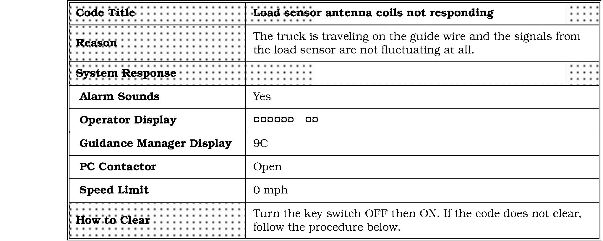
Code 9,C
Code 9,C
Corrective Actions and Checks


Code 9,F


Corrective Actions and Checks
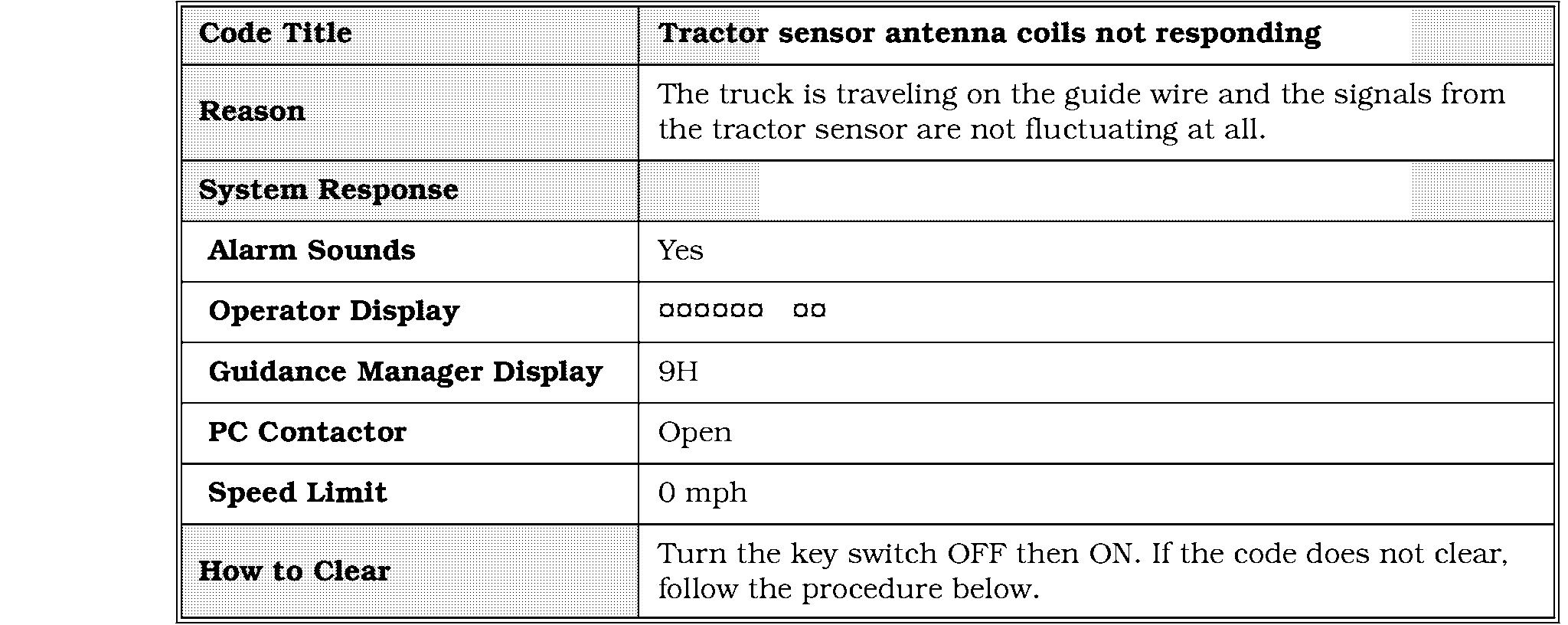
9,H
Code 9,H
Corrective Actions and Checks
Code 9,J
Corrective Actions and Checks

Code 9,K
Corrective Actions and Checks

Speed Feedback Encoder Test
This test should be run when the guidance system is not functioning properly.
1. Verify the speed feedback encoder is mounted securely to the drive motor.
2. Jack and block the truck.
3. Enter maintenance mode and travel slowly. See " Maintenance Mode" on page 6 - 4. The rate of horn chirps should increase as travel increases. Test the encoder in both travel directions.
a. If the chirp rate does not change as travel speed changes, or if there are no horn chirps, go to step 4.
b. If the chirp rate changes with the travel speed, the speed feedback encoder is good.
4. Manually flex the encoder wires and listen to the chirp rate.
a. If there are inconsistencies in the chirp rate, check the wiring from JH6 to JS1 for continuity or damage. Repair or replace faulty wiring.
b. If there are no inconsistencies in the chirp rate, replace the encoder assembly.
5. Verify 12 volts is available at JPS1-19 on the steer controller. If not, replace the steer controller.
6. Verify DGND is available at JPS1 - 12 on the steer controller. If not, replace the steer controller.
7. Rotate the speed feedback encoder while checking JPS1 - 8 with respect to JPS1 - 12. As the encoder rotates, the voltage should change between approximately 12 and 0 volts. If the voltage does not change, replace the encoder.
8. Rotate the speed feedback encoder while checking JPS1 - 7 with respect to JPS1 - 12. As the encoder rotates, the voltage should change between approximately 12 and 0 volts. If the voltage does not change, replace the encoder.
9. If voltages are good in steps 7 and 8, replace the guidance manager.
Steer Feedback Encoder Test
This test should be run when the guidance system is not functioning properly.
1. Verify the steer feedback encoder is mounted securely to the steer motor.
2. Enter maintenance mode. See " Maintenance Mode" on page 6 - 4.
3. Step on the deadman pedal and rotate the steering wheel at different rates of speed.
4. The rate of the horn chirps should increase as you turn the steering wheel faster.
a. If the chirp rate does not change, or the horn does not chirp, go to step 5.
b. If the chirp rate does change with the steering rate, the encoder is good. Do not finish the test.
5. Check the wiring from JH7 to JT6 for continuity or damage. Repair or replace faulty wiring.
6. Verify 5 volts is present at JPT6-3. If not, change the steer/tractor manager.
7. Verify DGND is present at JPT6-2. If not, change the steer/tractor manager.
8. Measure the voltage at JPT6- 1 with respect to JPT6-2 and turn the steering wheel. The voltage should cycle between approximately 5 and 0 volts as the encoder turns. If not, replace the steer feedback encoder.
9. Measure the voltage at JPT6-4 with respect to JPT6-2 and turn the steering wheel. The voltage should cycle between approximately 5 and 0 volts as the encoder turns. If not, replace the steer/tractor manager.
Wire Guidance Sensor Test
This test should be run when the guidance system is not functioning properly. This test assumes that all other components of the guidance system have checked good.
Tests
1. Park the truck directly over the guide wire.
2. Turn the key switch OFF.
NOTE: To test each sensor, you must enter a horn code-one for the load sensor, one for the tractor sensor. Once you enter the code, you can test coils individually in each sensor.
3. Enter the horn code to test the tractor or load sensors. To switch between tests, turn the key switch OFF before entering the other code. Load Sensor Tractor Sensor a. Hold down the horn button and turn the key switch ON. Do not release the horn yet. b. Wait for the steer LEDs to stop flashing, and release the horn button. c. Press and release the horn button the number of times as the first digit of the horn code. Each time you press the button, an addition BDI LED will light. d. Wait for the BDI LEDs to turn off. e. Press and release the horn button the number of times in the second digit of the horn code. f. Wait for the BDI LEDs to turn off. a. If one or more channels are low, re - learn the guidance offsets (page - 10) and repeat the test. b. If one or more channels are still low, swap the sensor input connectors on the filter card at JPWl and JPW2. c. If the low channel changes to the other end of the truck, test the cable for continuity shorts between wires, and shorts to frame. Include the shield wire at pin 13 in PW1 and PW2. If the cable tests good, replace the sensor.
NOTE: The steer LEDs indicate which coil is being tested. See Figure 8 -18. To change the coil being tested, press the horn button. The battery LEDs indicate the signal strength of each coil. See Figure 8 - 18.

4. Check the near wire coil pairs and verify the signal strengths are approximately the same.
5. Check the 4 guidance coils (2 right, 2 left) and verify the signal strengths are approximately the same.
6. Drive the truck diagonally across the guide wire to monitor the guidance channels. The signal strength should increase as the coil approaches the wire, and decrease as the coil moves farther away from the wire.
If the low channel stays the same, replace the filter card and re - learn the guide wire frequency and offsets. If the low channel stays the same after replacing the filter card, replace the steer controller.
Drive away from the wire and operate all truck functions, including travel, lift, steering, horn and any optional equipment while checking the guidance coils. If the guidance signal increases due to the operation of any of these functions, there is a short to frame in the truck or electrical noise generated by motors due to bad brushes, worn commutators or faulty suppressors. The sensor coils are picking up this noise.
8. Locate and repair the short to frame or faulty component.


