
2 minute read
Section 7. Component Procedures


List of Component
Toyota Orderpicker Model 7BPUE 15 Service Manual
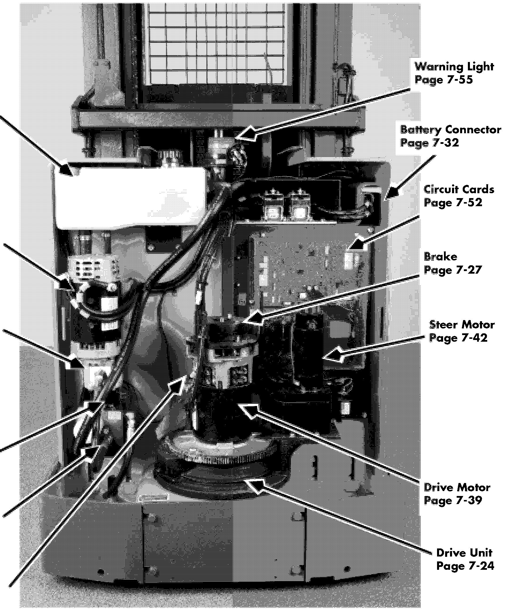
Component Locator Photos
Component Locator Photos
Side Cylinder Chains Mast Guard Page 7 - 9 1, page 7 - 93 Page 7 - 13
Side Cylinders Page 7-65
Section 7. Component Procedures
Center Cylinder Page 7 - 69
Forks Page 7 - 94 pallet Clamp Page 7-95
Hydraulic Reservoir Page 7 - 59
Lift Motor Page 7-41
Lift Pump Page 7 - 62
Solenoid Valves 4 Page 7 - 61
Hydraulic Manifold Page 7 - 58
Power Cables


Tractor Covers
Covers and Finish
Tractor Covers
Removal
1. Press in the two latch buttons then lift the top cover straight up and out. See Figure 7- 10.
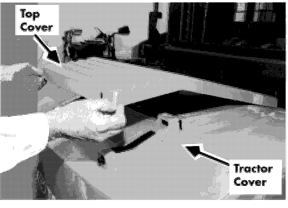
2. Pull out the tractor cover from the top.
Installation
1. Position the bottom of the tractor cover inside the bumper and push in from the top.
2. Position the top cover over the two latch buttons and push down until they snap into place.
Section 7. Component Procedures
Toyota Orderpicker Model 7BPUE 15 Service Manual
Operator Console Cover Covers and Finish
Operator ConsoleCover Installation
1. Position cover over console components and secure to the platform with - the two captivating knobs.

Make sure the operator platform is fully lowered before placing any part of your body between the masts.
Covers and Finish
Mast Guard
Removal
1. Lower platform fully to floor. Turn key switch OFF and disconnect battery.
2. Loosen four screws in each mounting bracket to gain clearance for mast guard.
3. Lift up mast guard until notches in mast guard clear the mounting brackets.
4. Pull screen guard forward to remove.
Installation
1. Insert screen guard over the 4 mounting brackets.
2. Lower guard until brackets align just above the opening. See Figure 7- 13.
3. Tighten all 6 mm socket head screws using an Allen wrench.


Operator Display
Operator Display
Replace
1. Turn key switch OFF and disconnect battery.
2. Remove operator console cover.
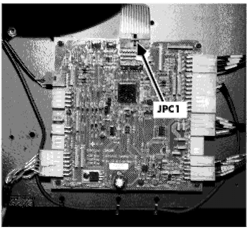
3. Disconnect the JPC 1 from carriage manager. See Figure 7- 15.
4. Peel failed operator display from console bezel.
5. Place new operator display in cut - out on console bezel.
6. Connect JPC 1 to carriage manager. See Figure 7 -15.
7. Install operator console cover.
Steering and Controls
Control Handle
For replacement parts, refer to the parts manual for the truck the handle is installed on.
Removal
1. Turn the key switch OFF and disconnect the battery connector.
2. Disconnect JPC9 and remove the Control Handle from the truck.
NOTE: Observe orientation of switches/ potentiometers and routing of cables/wires as the handle is
Be sure to observe proper precautions against electrostatic discharge. See "Static Safety" on page 2-9.
Before disassembly, determine which components require replacement:
Lift/Lower Potentiometer (Pot),Lift Spring, and/or Horn Switch

Travel Pot and/or Gear
Travel Spring, Shaft Gear, and so on Lift/Lower Knob
Lift/Lower Pot (VRZ), Lift Spring and/or Horn Switch Replacement
Disassembly
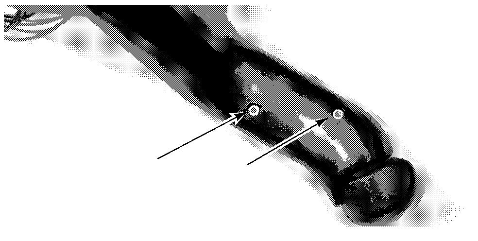
1. Remove the two 3/32 socket head nylon set screws in the lift/lower knob (thumb lever). If stripped, use a small 1/8 in. blade flat screwdriver and carefully back out the set screw.
2. Loosen the two metal set screws in the lift/lower knob two full turns and remove the lift/lower knob.
Control Handle

NOTE: Carefully slide the two spacer washers, lift/lower spring, and third spacer washer off of the lift pot shaft. See Figure 7 - 16.
3.
NOTE: Before sliding the pot bracket off the pot shaft, identify which slot in the pot bracket is used to hold the pot anti - rotate tab. The anti - rotate tab


