2 minute read
Section 9. Theory of Operation Toyota Orderpicker Model 7BPUE 15 Service Manual


Closing Deadman Switches
Closing Deadman Switches
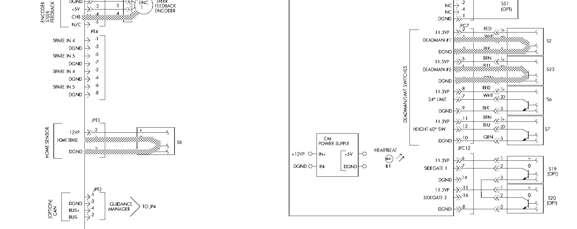
Stepping on the deadman pedal closes deadman switches S2 (Deadman 1) and S23 (Deadman 2). Both switches must be closed to travel, lift/lower and/or steer. If either switch opens while traveling, the travel command to the traction power amplifier stops and the brake is applied.
1. With S2 closed, a circuit is completed between JPC7 - 3 and JPC7- 1 on the carriage manager.
2. With S23 closed, a circuit is completed between JPC7 - 6 and JPC7 - 4 on the carriage manager.
3. With the S2 (Deadman 1) circuit complete, the micro processor on the CM detects that the switch is closed. The carriage manager communicates to the steer/tractor manager via the transmit line that switch S2 is closed.
4. The Deadman 2 input from S23 is wired directly through the mast cable from the carriage manager (JPC8-5) to the steer/tractor manager (JPT9-5).The CM does not look at the input or use it for anything.
5. The Deadman 1 message and Deadman 2 input are received by the steer/tractor manager and monitored continually to ensure they both agree. If only one of the switches closes while the pedal is depressed the operator display indicates a fault. LEDs on the steer/tractor manager for Deadman 1 (IL6-10) and Deadman 2 (IL2) are lit when the switches are closed.
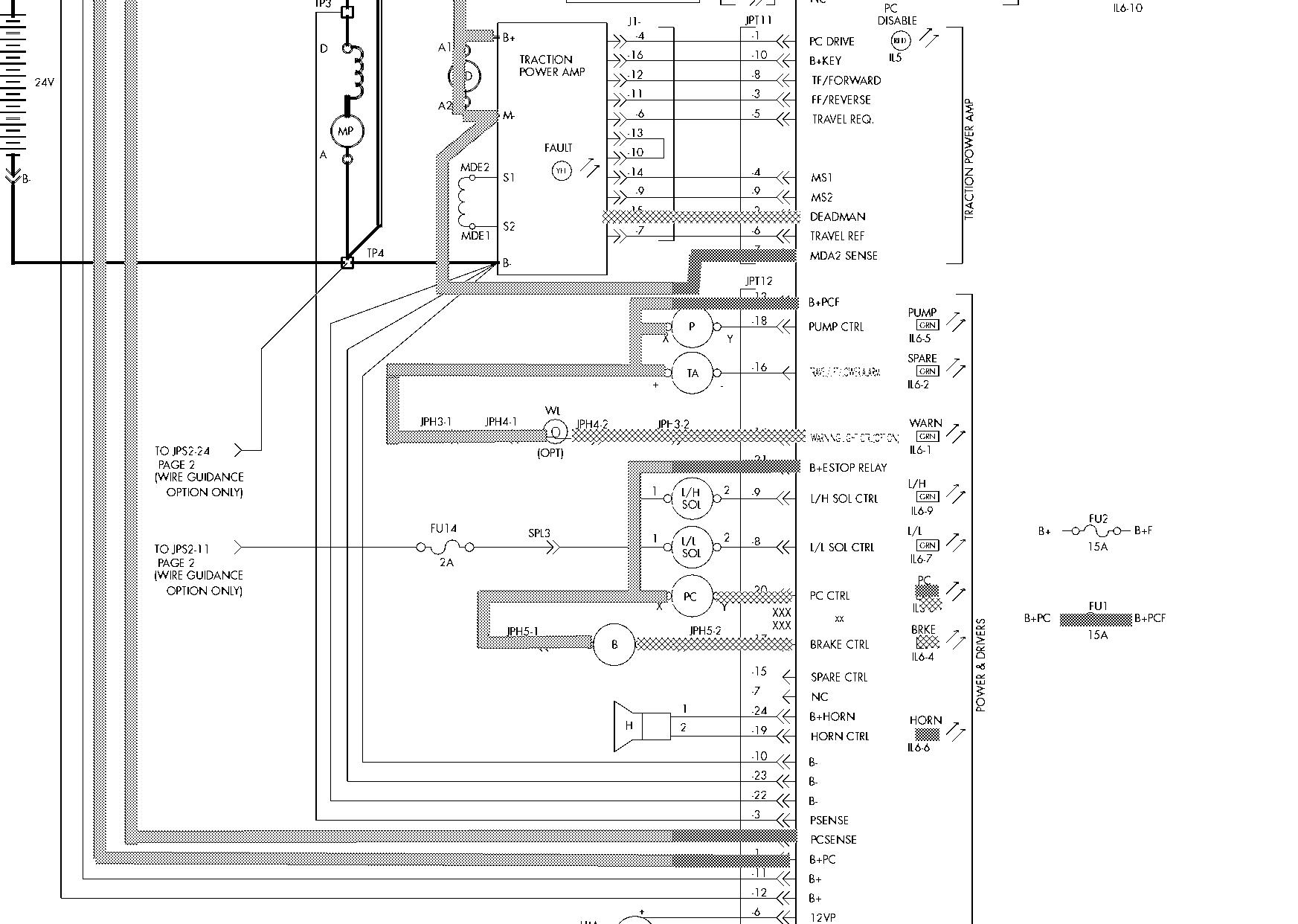
6. After the steer/tractor manager determines both Deadman switches agree, it turns on the PC contactor coil driver which is indicated by an LED (IL6-8).With this coil driver on, a current path is completed between JFT12-21 and JFT12-20 which energizes the PC contactor coil.
7. The PC contactor tips close and battery voltage is supplied to the following:
B+ side of the open pump (P) contactor tips, P-1
MHA-1 on the steer power head
Drive motor (MD) armature terminal A1
B+ terminal of traction power amplifier
M- terminal of traction power amplifier
Drive motor (MD) armature terminal A2
MDA2 sense at JPT11-7
JPT12-1 as B+PC
FU 1 as B+PC and B+PCF
JPT12-2 as PCSENSE
JPT12-13 to pump contactor coil (X) terminal as B+PCF
JFT12-13 to warning light as B+PCF (optional)
8. The steer/tractor manager also turns on the brake coil driver which is indicated by an LED (IL6-4).With this coil driver on, a current path is completed between JPT12-21 and JPT12-17 and the brake releases. If the Deadman switches are opened during travel the brake will be applied immediately.
9. After the truck has completed self-diagnostics and the deadman pedal is depressed, the STM looks at the input from the Home Reference Proximity Sensor. If the prox is over metal, the STM will turn the drive unit to the left. As soon as the prox switch transitions from metal to no metal the STM removes the steer command. If it is not over metal, the drive unit turns to the right. Once the home prox transitions from off to on, the STM turns the drive unit back to the left until the switch transitions to no metal and removes the steer command. This position is considered center and the position register for the steer feedback encoder is set to a zero reference point. During the auto steer center function, the STM monitors the steer feedback encoder and the steer motor current to verify the drive unit is actually powered and moving in the proper direction. If the STM does not see current or encoder pulses, an error code displays. If the STM does not see a home reference proximity sensor transition, it turns the drive unit to the physical stop. Current limit is invoked and an error code is displayed.
10. The STM places the truck in a speed limit condition waiting to see inputs from the steer tiller. 00700
Closing Deadman Switches
Section 9. Theory of Operation
Closing Deadman Switches
Toyota Orderpicker Model 7BPUE 15 Service Manual
HOUR METER ENABLE
Tracine Legend - Electrical
= B+ Circuit
= B- Circuit
= Signal

WHHHHHHHHHHA = 1 2V/ 5V


Toyota Orderpicker Model 7BPUE15 Service Manual


Section 9. Theory of Operation
Closing Deadman Switches
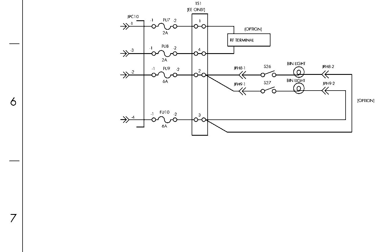
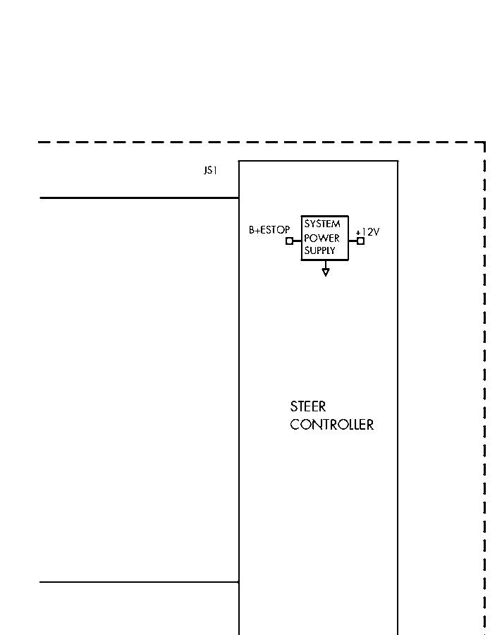
Figure 9-4 (Cont.). Closing Deadman Switches (Sheet 4 of 4)


Tracing! Legend - Electrical= B+ Circuit = B- Circuit= Signal VHMBMHHM = 12V/5V


