1 minute read
Section 9. Theory of Operation


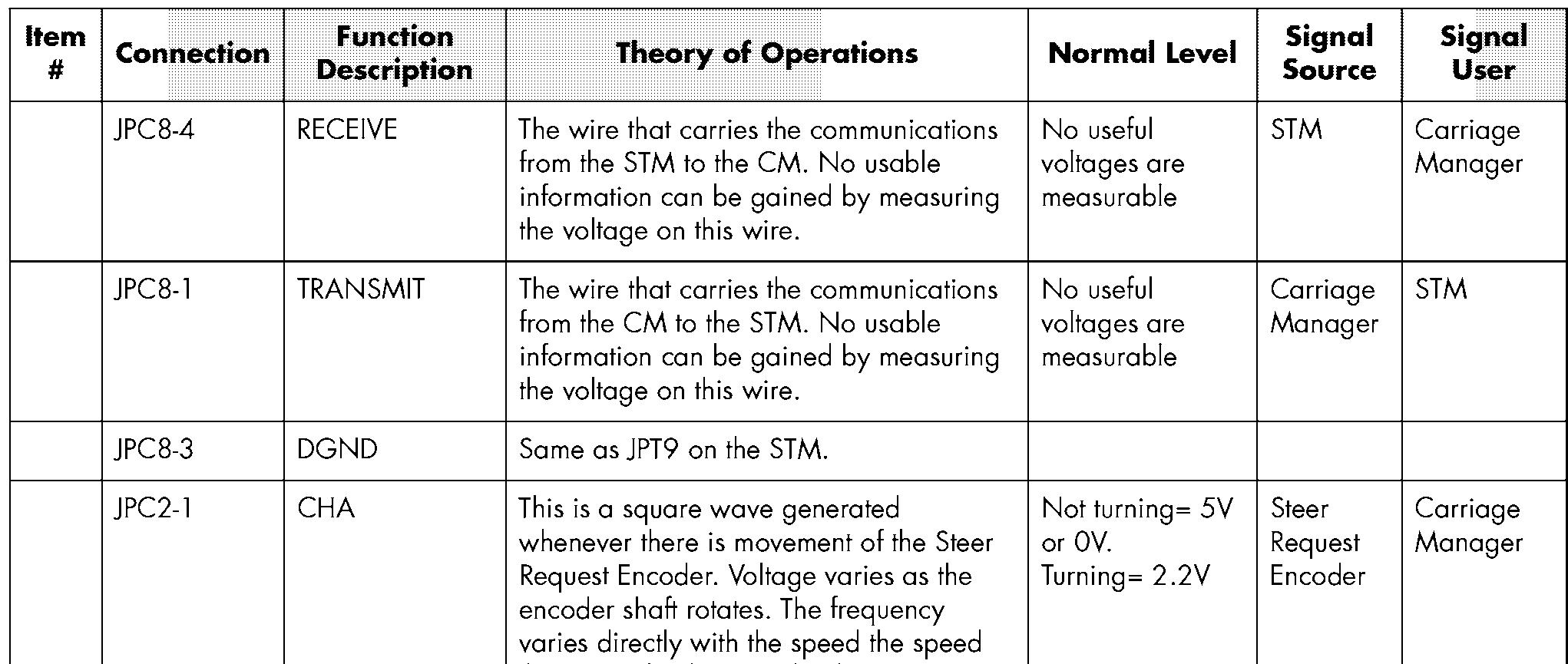
The CM uses the quadrature phase relationship between CH A & B to determine direction and speed of steering requested.
B- to the steer request encoder.
Positive supply from the CM power supply to the steer request encoder.
This is a square wave generated whenever there is movement of the Steer Request Encoder. Voltage varies as the encoder shaft rotates. The frequency varies directly with the speed the steer wheel is spun by the operator. The CM uses the quadrature phase relationship between CH A & B to determine direction and speed of steering requested.
Not connected to any circuitry on the CM.
Positive supply from the CM power supply for optional devices.
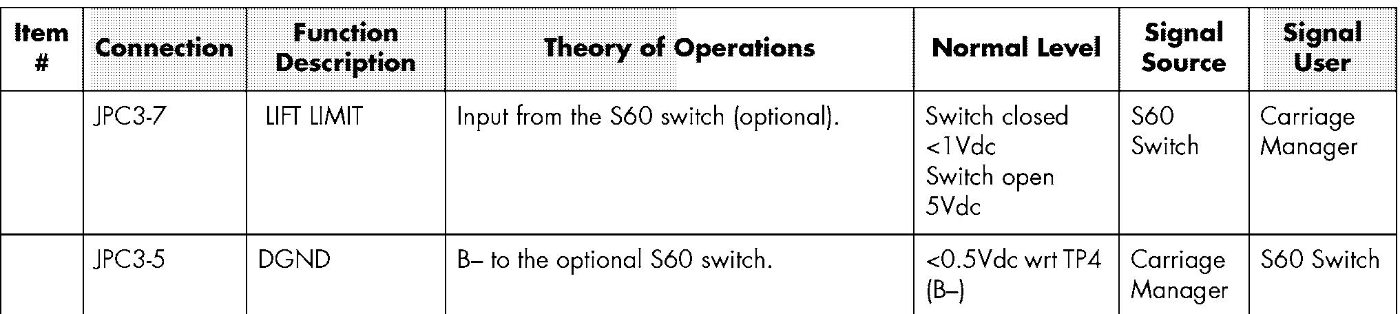
Input from the S10 switch (optional).
B- to the optional S10 switch.
Positive supply from the STM power supply for the optional S60 switch.
Not Connected
Input from the S61 switch (optional wire guidance auto manual switch).
B- to the S61 switch (optional wire guidance auto manual switch).
Not connected to any circuitry on the CM. Not connected to any circuitry on the CM.
Supplies B+ to the key switch on the carriage via the over mast cable. B+ is supplied from FU2 on the STM.
Supplies B+ Key to the circuitry on the Carriage Manager and STM via the over mast cable when the key switch is closed.
Supplies B+ Key to the EPO switch.
Supplies B+ ESTOP to the circuitry on the Carriage Manager and through the over mast cable to the STM when the EPO switch (S21 ) is closed.
Not connected to any circuitry on the CM. Supply voltage from the CM power supply for the Travel potentiometer VR1.
Variable voltage from VR1 wiper. The Carriage Manager monitors this voltage and translates it into a communication input to the STM. The STM determines the requested travel direction and speed based on the learn values stored in the STM.
B- for VR1, Travel potentiometer.
Supply voltage from the CM power supply for the Travel potentiometer VR2.


