
1 minute read
Section 8. Wire Guidance


System Overview
System Overview
Wire guidance is a means to automatically steer the truck while traveling in an aisle. It offers precise steering at full-speed travel in very narrow aisle (VNA)applications.
A wire guidance system consists of two sub - systems.
Warehouse - installed equipment includes a guide wire and line driver. The guide wire is in the floor and emits an alternating current (AC) signal at a specific frequency and amplitude generated from the line driver.
Truck - installed equipment includes:
Two guidance sensors, tractor end and load end
Steer controller, behind steer motor
Filter card, on guidance manager
Travel speed feedback encoder, on top of the drive motor
Steer feedback encoder, on top of the steer motor
Auto/manual switch, on operator console
Associated cables and mounting brackets
The truck must learn the amplitude and frequency of the guidance signal to properly track the guide wire.
NOTE: This manual will cover all truck - installed equipment.
To operate wire guidance, see the Model 7BPUEl5 Operator Manual.
Install Kit Components
Before installing kit components, turn the key switch OFF, disconnect the battery and remove the appropriate covers.
NOTE: Once you install all the components, complete the Set-Up Procedure beginning on 8 - 9.
Guidance Manager (Steer Controller Card and Filter Card)
The guidance manager is an assembly comprised mainly of a steer controller card and a filter card. The wire guidance firmware is housed in the WSI module.
1. Wear a static strap and insert the WSI module (P/N 00590 - 458 18 - 71) into the socket on the steer controller card. See Figure 8 -1.
4. Install the power and ground cable (P/N 00590 - 4588 1 - 71) to connector PS2 on the steer controller card. Route the wires through the wiring channel along the steer/tractor manager to SPL3 and TP4 as shown on the schematic. (See Figure A - 6 on page A- 13.) Use cable ties as necessary.
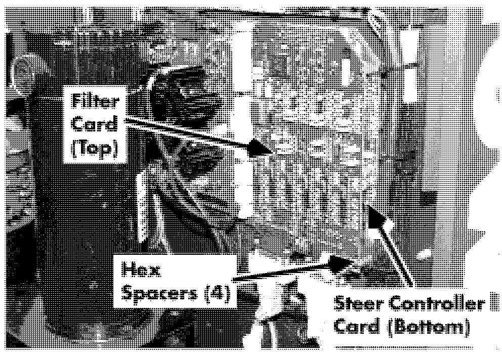
2. Install the steer controller card assembly (P/N 00590 - 459 10 - 71) on the electrical panel with four hex spacers (P/N 00590 - 02988 - 71). See Figure 8 - 2.
3. Install the filter card assembly (P/N 00590 - 45747 - 71) on the steer controller
5. Install the CAN bus wiring harness (P/N 00590 - 45881 - 71) to PS4 on the steer controller card. Route the harness along the existing wiring to the steer/tractor manager connector PT2. Use cable ties as necessary. card. Secure with four screws (P/N
00590 - 45925 - 7 1) in the hex spacers. See Figure 8 - 2.


