
4 minute read
Section


Steer Motor
Steer Motor
Inspection
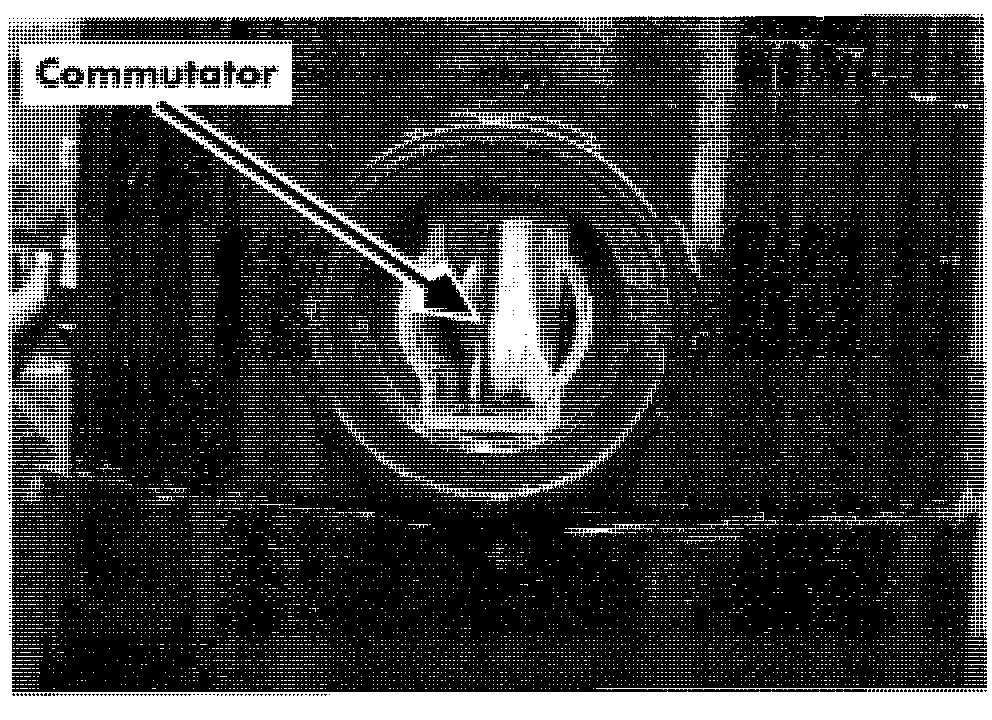
Check brushes. Once brushes are removed, check commutator. See Figure 7 - 60.
Electrical Components
9. Install new steer motor assembly on pivot ring. Secure with four bolts and adhesive (P/N 00590 - 04964 - 71). See Figure 7 - 6 1.
10. Install steer switches.
11. Connect M+ and M- to steer/tractor Figure 7 - 60. Steer Motor Commutator, Brushes Removed manager.
Replace
12. Install circuit card cover.
13. Connect power and test operation before
1. Turn key switch OFF and disconnect returning truck to service. battery.
2. Remove tractor covers. See " Tractor Covers" on page 7 - 1 1.
3. Remove circuit card cover.
4. Disconnect wires M+ and M- from steer/tractor manager.
5. Remove proximity switches and disconnect encoder.
6. Remove four mounting bolts and pull steer motor assembly off pivot ring. See Figure 7 - 61.

7. Remove six mounting bolts that secure motor to mounting Figure 7 - 62. Separating Steer Motor from Gear Box
8. Install mounting plate to steer motor using six bolts.
Disassembly
1. Remove steer motor. See "Steer Motor" on page 7 - 42.
2. Remove eight screws in the gear box. See Figure 7 - 62.
3. Replace parts as necessary. See Figure 7 - 63. 00700
Pinion Gear


Replace
Steer Motor
removed in step 3, and secure with the mounting bolt. Apply adhesive (P/N 00590-04964-71) on steer motor shaft. See Figure 7-65.
5. Install steer motor assembly. See "Steer Motor" on page 7-42.
6. Connect power and test operation before returning truck to service.
Traction Power Am ifier
Remove
1. Turn key switch OFF and disconnect battery.
2. Remove top and tractor covers.
3. Remove control panel cover. See Figure 7 - 66.
Section 7. Component Procedures
6. Remove traction power amplifier. See Figure 7 - 67.
Install
1. Install traction power amplifier on top of power panel on top of tractor. See Figure 7 - 67.

2. Secure traction power amplifier with three Figure 7 - 66. Top
4. Disconnect the following cables and bus bars: bolts.
3. Connect cables and bus bars. See Figure 7 - 67.
4. Install control panel cover. See Figure 7 - 66.

5. Install tractor and top covers.
6. Connect battery and turn key switch ON.
7. Test truck operation.
5. Remove three bolts.
Contactors
C~ntcl~t~r~
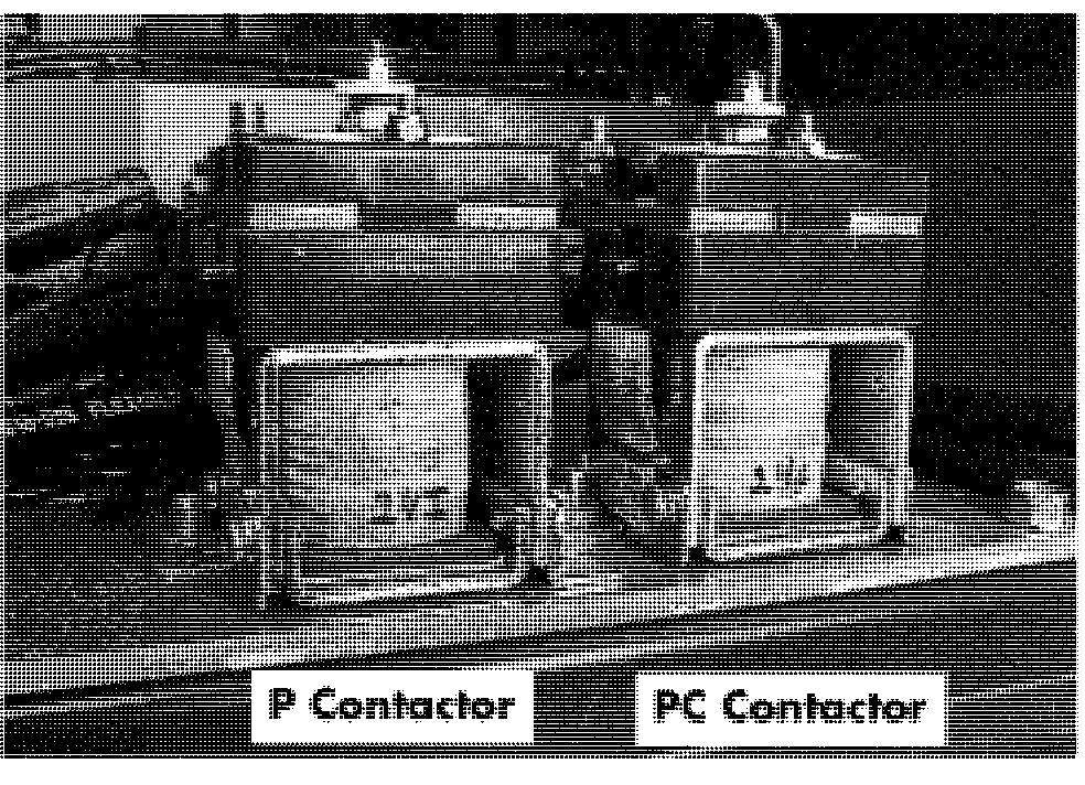
This lift truck has two contactors, the PC and pump (P) contactors. The following procedtzres
Remove Assembly
Electrical Components
Acaution
When repairing contactors, use only apply to either one. Toyota authorized contactor kits.
1. Turn key switch OFF and disconnect battery.
2. Remove tractor covers. See "Tractor Covers" on page 7 - 11.
3. Remove control panel cover. See Figure 7 - 69.

Tip Inspection
When you inspect contactor tips, follow these guidelines:
Disconnect the battery before inspecting or servicing contactor tips.
Darkened points do not indicate burning. Burning indicates a loss of contact point
4. Identify contactor to be removed. See material. Figure 7 - 71.

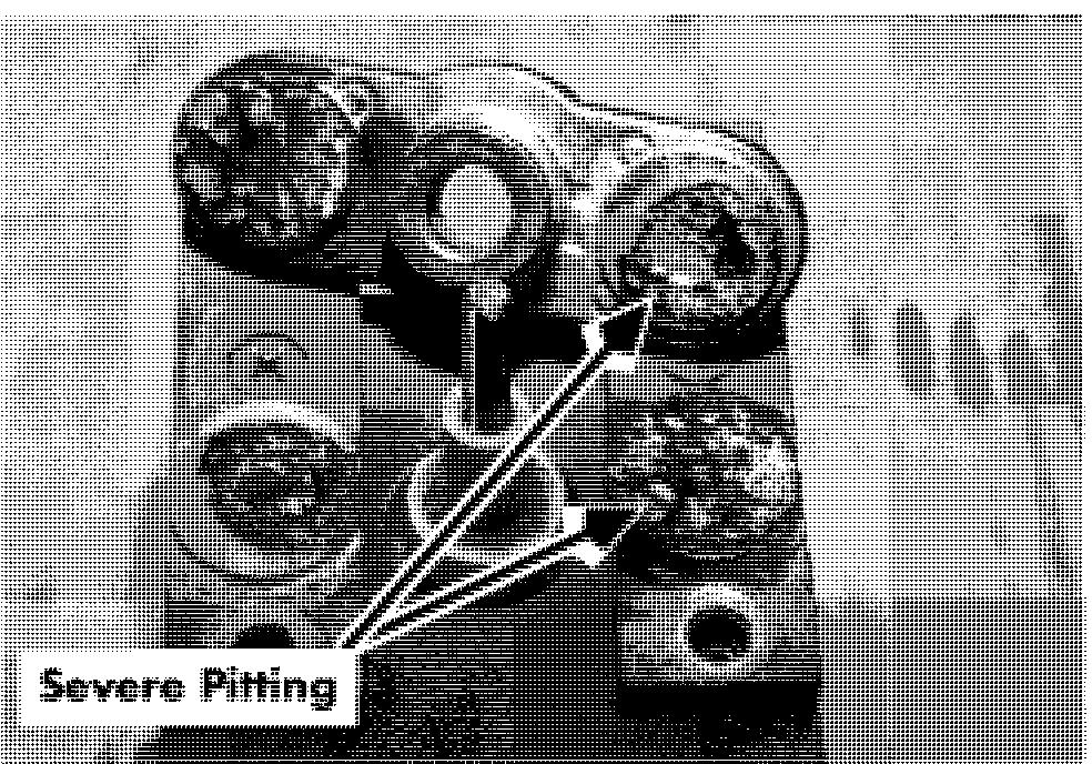
Replace the contact tips if there is not enough contact point material to last until the next regular inspection or severe pitting is evident. See Figure 7 - 68.
The silver alloy part of the point is usable contact material; the copper backing is not.
Do not file contact tips to remove discoloration or minor irregularities. This practice produces a surface more susceptible to sticking.
If a cone and crater appear, remove the cone with a file; Do not use sandpaper or emery cloth.
5. Disconnect appropriate cables and fuses by removing hex nuts. Note their location
Electrical Components and label if necessary for proper reinstallation. See Figure 7 - 71.
6. Remove bus bars between contactors. See Figure 7 - 70.
7. Remove contactor coil wires (X and Y) by pulling wire connector. Note their locations and label if necessary.
8. Remove contactor from mounting panel (2 hex nuts).
Install Assembly
1. Position the contactor on the threaded studs of the mounting panel and attach with hex nuts. See Figure 7 - 71.
NOTE: P contactor is intermittent duty; PC contactor is continuous duty.
2. Attach coil wires (X and Y) by sliding connector onto appropriate spade terminal.
3. Install bus bars on contactor lugs.
4. Install fuses. Match location to corresponding tractor frame label.
5. Attach cables to appropriate lugs and tighten securely.
6. Connect power and test operation before returning truck to service.
Contactors
Contactor Tip Replacement
Disassembly
7. Remove nylon nuts (2) securing upper retaining blocks (2).See Figure 7-73.
8. Remove upper retaining blocks. For the PC and pump contactors, use the

9. Remove stationary tips (2). proper contactor tip replacement kit

10. Remove nut on top of core and rod (P/N 00590-02782-71). It contains the following assembly shaft. See Figure 7-73. items:

2 stationary contact tips
1 movable contact tip
1 contact spring
1 fiber washer insulator bushing
When replacing contactor tips, replace all old parts with the parts supplied in the kit, even if the old parts appear to be good.
11. Remove fiber washer.
12. Remove contact spring.
13. Remove movable contactor tips.
14. Remove insulator bushing.
Replacement
1. Install new insulator bushing over core and rod assembly shaft. See Figure 7-74.
2. Install new movable tips over insulator bushing, with contact tip faces down.
Electrical Components Contactor Tip Replacement
3. Install new contact spring over insulator bushing.
4. Install new fiber washer over rod assembly shaft.
5. Secure movable tip assembly with nut on top of core and rod assembly shaft.
6. Install new stationary contactor tips (2), with tips facing up.
Make sure cable posts face up, and are on same side as contactor coil spade terminals.
Make sure studs on lower retaining block lock into holes in contact tip bar.
7. Install upper retainer blocks (2).Studs on blocks will lock into holes in contactor tips. See Figure 7-75.
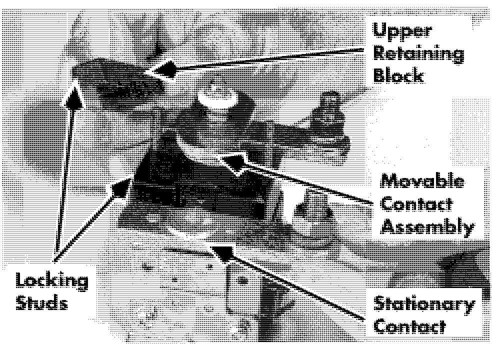
NOTE: Grooves on the retainer blocks face the inside.
8. Secure upper retainer blocks with nylon nuts.


