
3 minute read
General Troubleshooting


To troubleshoot poor performance of wire guidance when no fault code is generated, follow these corrective actions and steps.
NOTE: In the following step, consult the battery manufacturer's recommendations for the specific gravity. If unavailable, use the value stated in step 1.
1. Check the battery for an adequate charge. If the specific gravity is less than 1.145, replace or charge the battery. Adjust the BDI cutout correctly.
2. Check for shorts to frame.
3. Check the static strap. Clean or replace as necessary.
4. Make sure both guidance sensors are mounted on the truck centerline with no physical damage.
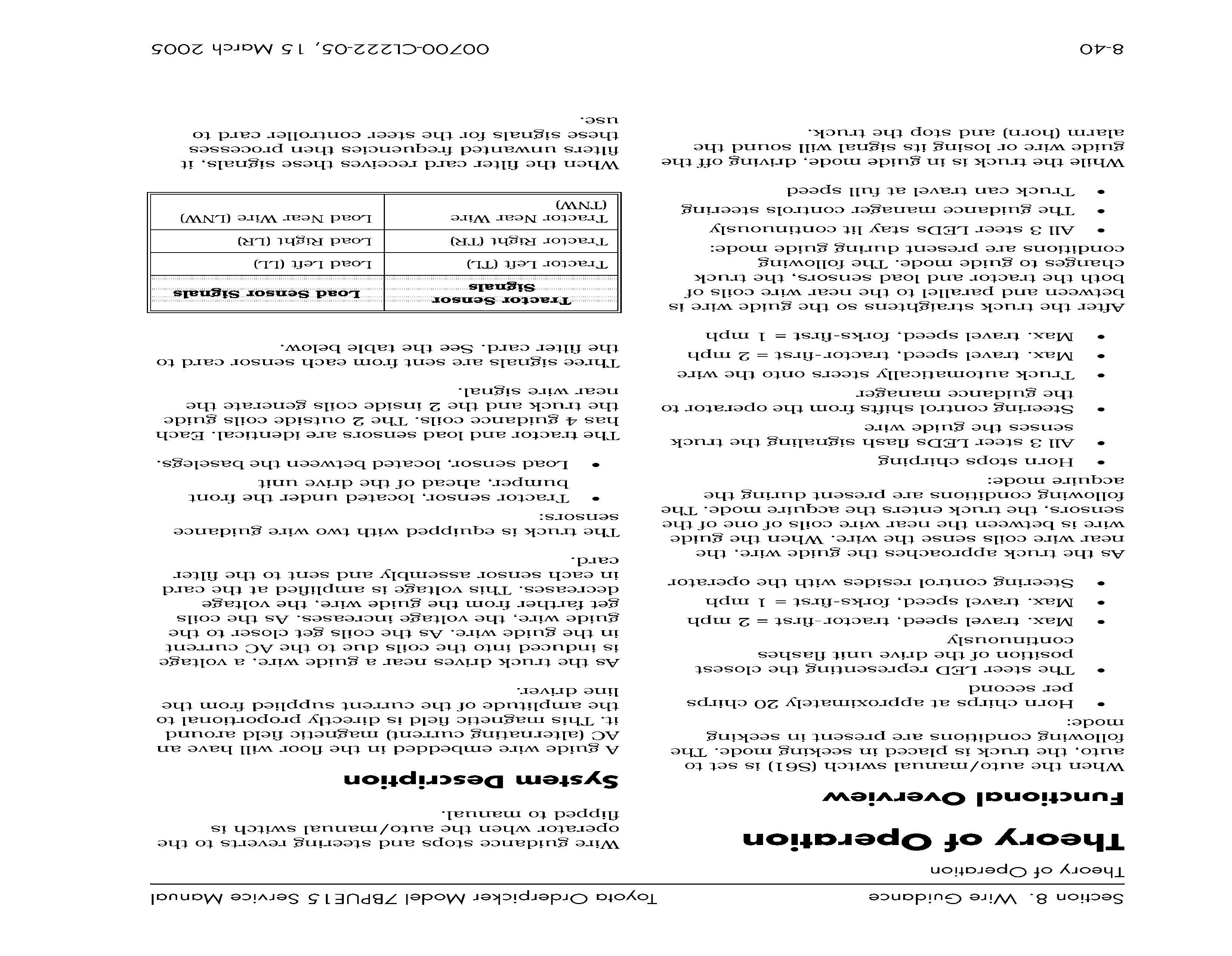
5. Make sure the sensor cables are not connected backwards to the guidance manager.
6. Make sure the line driver is adjusted according to the manufacturer's specifications.
7. Relearn the wire guidance frequency and offsets. See page 8 - 10 and page 8 - 10.
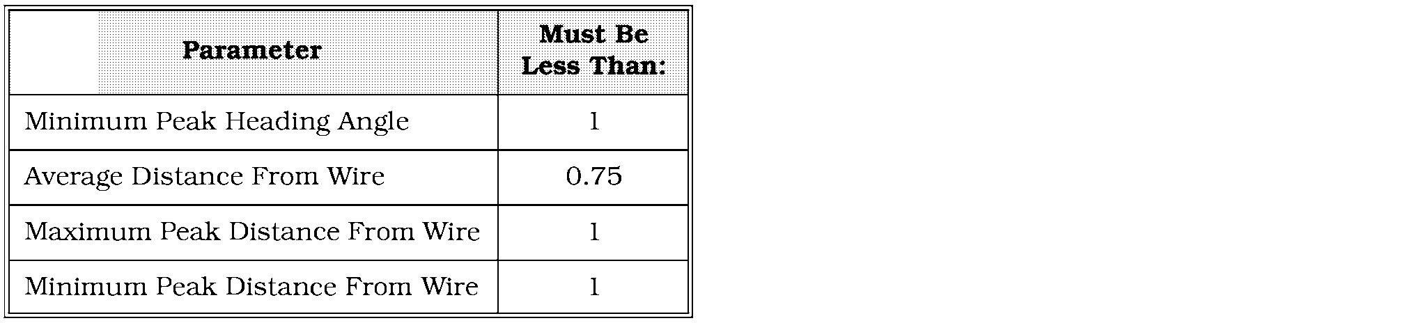
8. Make sure the heading angle and distance from wire settings are configured correctly. See "Guidance Parameter Setup " on page 8 - 9.
9. Check for bent base legs.
10. Make sure the load wheels are not binding.
11. Check for excessive play in the drive unit radial ring.
12. Make sure the steer motor is securely mounted to its gear reducer.
13. Make sure the steer motor gear reducer is not binding and its pinion gear is properly engaging the drive unit.
NOTE: Switching from manual to auto mode clears the values for the parameters above.
00700-CL222-05, 1 5 March 2005
Theory of Operation
The steer controller compares the strength of The HA and DFW settings may be changed in four guidance signals (TL,TR, LL, RR) and the Truck Configure Menu using Flashware determines the truck's distance from wire software. See "Options" on page 10 - 9. (DFW) and heading angle (HA).The steer controller uses the DFW and HA to correct the When the steer controller calculates the HA and steering via the tractor steer manager. DFW, it sends a steering correction request tothe steer/tractor manager via the CAN-bus (BUS+, BUS-). The steer/tractor manager then tells the steer power head which direction to steer. This command causes the drive unit to turn.
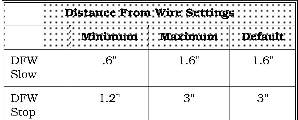
For example, if the steer controller calculates that the truck is 1" to the right of the wire, it The heading angle is the angle between the tells the steer/tractor manager to turn the drive direction the truck is pointed and the guide unit and move the truck toward the left until all wire. The steer controller calculates the angle 4 guidance signals (TL,TR, LL, LR) are equal by comparing the TL, TR, LL and LR signals. distance from the wire. For example, if the TL and LR signals are stronger than the TR and LL signals, the truck is pointed to the right of the guide wire. This calculation is compared to the configured settings of HA slow and HA stop. If HA slow is 1.6" and if the heading angle is greater than 1.6", travel speed is limited. If HA stop is 3" and the heading angle is greater than 3", travel will come to a controlled stop.
While the drive unit is turning, the steer feedback encoder reports the amount the drive unit is turning. This encoder is mounted directly on the steer motor's armature shaft and rotates with the steer motor. As the encoder turns, it sends two voltages, CHA and CHB, to the steer/tractor manager. The steer/tractor manager uses these voltages to track the drive unit position, then sends the information to the steerLcontrollervia the CAN bus. CHA and CHB change state from approximately 5 volts to 0 volts and back as the encoder rotates. The resulting number of times the 2 channels change state indicates how far the drive unit has turned. When the required amount of turning is sensed, the steer command is removed.
Distance from wire (DFW) is the distance the centerline of the truck is from the guide wire. The steer controller calculates this distance by comparing the TL, TR, LL and LL. For example, if the TL and LR are stronger than the TR and

The steer controller also verifies the direction the drive unit is turning. CHA changing state before CHB indicates one direction. CHB changing state before CHA indicates the opposite direction.
Since the truck travels in relationship to the the guide wire than the right guidance coils. wire, once a steer request is carried out and the The factory default settings for DFW slow is truck moves forward, the sensors' relationship 1.6". If this distance is greater than 1.6'', travel to the wire changes, therefore the steer request speed is limited. The factory default setting for changes. The change in request will turn the DFW stop is 3 " . If the distance is greater than drive unit the other way, monitored by the steer 3", the travel will come to a controlled stop. feedback encoder, until the truck is both parallel to and directly over the wire.
LR signals, the left guidance coils are closer to


