
9 minute read
Shorts to Frame Test


" Shorts to frame" is an industry term for unintentional current leakage paths between normally isolated electrical circuits and their metal enclosures.
Shorts to frame may be metallic connections, such as a wire conductor contacting metal through worn insulation. More often, shorts to frame are resistive "leakage" paths caused by contamination and/or moisture.
These leakage paths can result in unwanted electrical noise on the metallic truck structure, and may result in improper operation.
Shorts to frame can be caused by:
Accumulation of dirt
Battery electrolyte leakage
Motor brush dust
Motor brush leads touching the housing
Breakdown in insulation
Bare wires
Pinched wiring harness
Improper mounting of circuit cards
Shorts to frame can occur at numerous locations on a truck, including:
Batteries
Motors
Cables, wiring, and harnesses
Heat sinks
Bus bars
Solenoids
Contactors
Terminal strips
Switches
Power panel insulation
Circuit card mounts
To determine the source(s) of shorts to frame, begin by testing the battery for shorts to case.
Then test for shorts between electrical components and the truck frame.
To test for shorts to frame: a. To identify the cause of the short to frame, disconnect circuit components until the low resistance condition disappears. Do not reconnect components one at a time, but leave them disconnected until the low resistance reading disappears. Prevent disconnected terminals or connectors from touching the truck frame or other conductive surfaces. b. The most likely areas to check are:
1. Turn the key switch OFF and disconnect the battery connector.
2. To test the battery for shorts to case, connect a 12-volt test light to the battery case from battery B+, and then to the battery case from battery B- If the light lights at all, even momentarily, there is a serious problem with the battery, either external contamination or internal damage. DO NOT continue until this condition is corrected. Your meter may be damaged if you proceed before correcting this condition. Install another battery in the truck and repeat this procedure from step 1. If the test light does not light, continue to the next step.
3. With the battery disconnected from the truck, use a digital ammeter to measure the leakage current from the battery case to battery B+ and from the battery case to battery B-. Begin measuring at the highest ampere scale and work toward the lowest. A reading of more than 0.00 1 A (1 mA) indicates a serious short. DO NOT continue until this condition is corrected. Your meter may be damaged if you proceed before correcting this condition.
Install another battery in the truck and repeat this procedure from step 1.
If the current is less than 0.0002 A (0.2 mA), go to step 4. If the current is greater than 0.0002 A (0.2 rnA) and less than 0.001 A (1 rnA), remove the battery from the truck, then continue with step 4. Ensure the battery case does not touch the truck frame during the remaining tests.
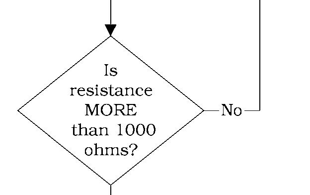
4. With the battery disconnected (or removed and disconnected) from the truck, use a digital ohmmeter to measure the resistance from truck frame to truck B+, to truck B- (NOT battery B+ and B-), and to all fuses and motors. A reading of less than 1000 ohms indicates a serious short.
DO NOT continue until this condition is corrected. Your meter may be damaged if you proceed before correcting this condition.
NOTE: Depending on the nature of the problem, it may also be necessary to measure for shorts to frame, B+ (truck) or B- (truck) at specific circuits associated with the problem.
Motors
Heat sinks
Power cables
Power circuit components
Control circuit components c. Repair or replace the component causing the low resistance condition, Then repeat Step 4. d. Reconnect all other components previously disconnected, one at a time, measuring resistance between steps. If a reading is less than 1000 ohms when reconnecting a component, that component or its wiring is defective; repair or replace as appropriate. e. When, after all components are reconnected, you get readings greater than 1000 ohms, continue with the next step.
5. Reconnect the battery connector to the truck and turn the key switch ON. If the battery was previously removed, ensure the battery case does not touch the truck frame.
6. Use a volt/ohm/ammeter on the current function meter to measure leakage current to the truck frame from B+, B, and all
Shorts to Frame Test
fuses and motor terminals. Begin measuring at the highest ampere scale and work toward the lowest. If the current is less than 0.001 ampere (1 mA), go to step 7. If the current is more than 0.001 ampere (1 mA), continue with the step below.
a. To identify the cause of the short to frame, disconnect circuit components until the leakage current reads less than 0.001 A (1 mA). Do not reconnect components one at a time, but leave them disconnected until the leakage current reads less than 0.001 ampere (1 mA). Prevent disconnected terminals or connectors from touching the truck frame or other conductive surfaces.
b. The most likely areas to check are:
Motors
Heat sinks
Power cables
Power circuit components
Control circuit components c. Repair or replace the component(s) causing the leakage current. Repeat step 6. d. Reconnect all other components previously disconnected, measuring current between steps. If a reading is more than 0.001 A (1 mA) when reconnecting a component, that component or its wiring is defective. Repair or replace as appropriate.
7. When, after all components are reconnected, you get a reading less than 0.001 ampere (1 mA) there is no short to frame condition with the truck or the battery. If you previously removed the battery from the truck, re - install the battery.
Section 5. Troubleshooting Toyota Orderpicker Model 7BPUE 15 Service Manual


Shorts to Frame Test
Shorts to Frame Test
Turn the key switch OFF and disconnect the battery connector.
With battery connector disconnected, measure leakage current from battery case to battery B+ and to current setting of meter, then


Connect a 12V test light from battery case to battery B+, then from case to battery B-
Remove battery from truck. Go to Chart
With battery connector disconnected (or disconnnected/removed) , measure resistance from truck frame to truck B+, to truck B(NOT battery B+/B-), & to all fuses & motors.

Do NOT continue until resistance measures greater than 1000 ohms, or meter damage
Shorts to Frame Test
Disconnect a circuit component and measure resistance again. (Do not reconnect previously disconnected components.)


Reconnect the battery connector. Turn key switch ON.
Disconnect a circuit component and measure current again. (Do not reconnect previously disconnected components.)

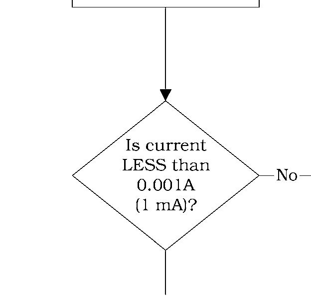

Measure leakage current to truck frame from B+, B-, all fuses and motors.
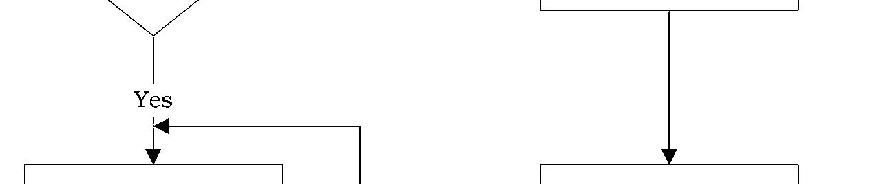
Yes
Repair or replace the component last disconnected. Reconnect all components one at a time, measuring current between steps.
Yes
Repair or replace the component last disconnected. Reconnect all components one at a time, measuring resistance between steps.
Yes I shorts to frame. Reinstall battery if previously removed.
Troubleshooting Wiring Problems
Troubleshooting Wiring Problems
Visually inspect all wiring and electrical components for:
Loose connections or connectors
Loose or broken terminals
Damaged terminals, blocks, or strips
Exposed wire at terminations, excessive strip gap
Abrasions, scrapes, nicks in the wire, damage from overheating or burns, or other general insulation damage move a harness, cut a cable tie, or remove the wire from a bracket. Note carefully the location of the wire and all protective or securing attachments before moving the harness.
After repair, return or replace all protective and/or securing hardware to its original condition. Protective materials are necessary for the interconnect system to perform reliably.
Examine and maintain any added materials used to dress or protect the wire. This includes spiral wrap, brackets, cable ties, fasteners, flexible conduit, etc.
Do not attach tie wraps tight enough to pinch or deform cable harnesses. Avoid tie wrapping Broken wire strands and shorted hydraulic hoses which expand with pressure to conditions (especially those that are close hinder extra pinching of tie wrapped electrical to metal edges or surfaces) cables.
Power Cables Inspection
Power cables should be checked for damage, including:
Evidence of overheating
Use a digital ohmmeter to check for wiring continuity.
Wiring Harness Terminology
Burned spots in the cable
Nicks or cracks in the insulation
Damaged or overheated terminal lugs
Damaged mounting hardware or brackets
The term "connector JPCx" or " connector JPTx" means a mated connector consisting of two connector halves. One half contains male connectors, or pins (P);the other half contains female connectors, or jacks (J).The third character references the relative location of the Repair or replace damaged cables or mounting Connections On the carriage hardware as necessary. manager are designated by a (C). Connections on the steer/tractor manager are designated by Power cables are marked on the terminal lug (T). Hanging connections are designated by (H). with the location where they belong. If the marking is missing or is not readable, remark When you a mated JP connector. the cable with the correct information. you will have two connector halves. The individual connector halves are designated by The terminal lugs should be crimped tightly and " Jx " and "Px." securely on the wire. Replace the lug if overheating is evident. Repair or replace faulty JPT3 is the mated connectors as necessary. connector for steer position feedback. 53 represents the jack connections, P3 represents
Guidelines
During troubleshooting and repairs, it is sometimes necessary to unplug a connector, the pin connections and T designates the steer/tractor manager.
Use the "Electrical Connector Locator Chart" on page 5-18 to locate electrical connectors on the truck.
Inspection
Whenever working on the truck, use care around wiring harnesses.
Do not pull on wires.
Carefully mate and unmate all connectors. Do not pry apart connectors with unspecified tools.
Examine and maintain any added materials used to dress or protect the wire. This includes spiral wrap, brackets, cable ties, fasteners, flexible conduit, etc. Check harness wires for abrasions, scrapes, nicks, damage from overheating or burns, or other general insulation damage.
Replace terminations with exposed wire visible at the connectors. Damaged terminations, exposed wires or damaged connectors can cause operational failure of the truck.
During troubleshooting and repairs, it is sometimes necessary to unmate a connector, move a harness, cut a cable tie, or remove the wire from a bracket. Note carefully the location of the wire and all protective or securing attachments before moving the harness.
After repair, return or replace all protective or securing hardware to its original condition. Protective materials are necessary to provide reliable performance of the interconnect system.
There should be a wire marker at each termination. If the marker is missing or unreadable, remark the wire for easier identification.
NOTE: It is normal to find unused connectors for uninstalled options that have had heat shrink applied over them and have been strapped to the harness.
00700 - CL222 - 05, 1 5 March 2005
Section 5. Troubleshooting Toyota Orderpicker Model 7BPUE 15 Service Manual
Switches (General)
Switches (General)
Examine the switch for signs of arcing, overheating, discoloration, cracking, or other physical damage. Replace the switch if you see such damage.
To test a switch, isolate it from the electrical circuit. Do this by removing all the connections from the switch, making sure all wires are labeled and identified for reconnection.
Use an ohmmeter set to a low resistance scale to measure the resistance across the switch. In a closed position, the switch should be less than 1 ohm. In an open position, the switch should show a resistance greater than 10 megohms.
Hall Effect Switches
The limit switches and deadman switches used on this truck are Hall Effect switches. These switches consist of a transistor that is turned on when a magnet is positioned next to the base. (Keep in mind that the magnet is part of the switch assembly and can only be seen if the switch is disassembled.)

The switch is powered as follows: +6 to + 12 volts is applied to the positive (+) terminal.
Battery negative is applied to the negative (-) terminal.
As shown in Figure 5- 1, when a magnet is not present, the transistor is OFF and the output lead (Deadman # 1) is in a high state.

When a magnet is present, the transistor is turned ON creating a path from the DGND (-) terminal to the Deadman # 1 terminal. Terminal Deadman # 1 will now be a negative (-) potential, or active.

Key Switch Inspection
With the battery plugged in and key switch in the ON position, battery voltage B+ should be present on both terminals of the switch. Test the key switch with an ohmmeter after removing it from the electrical system. In the OFF position, the ohmmeter should read greater than 10 megohms, and in the ON position, the ohmmeter should read less than 1 ohm. If not, replace the switch.
Electric Motor Tests Shunt-Wound
S2lE2lD2
Motor Types
Refer to Figure 5 - 3.
A shunt - wound or series - wound drive motor has four external connections: two armature (A) and two field (S, E, or D).
A series - wound lift motor has only two external connections because the armature and field windings are connected internally.
Electric Motor Tests
A permanent magnet steer motor uses permanent magnets as fields and has only two external connections.
NOTE: Field connections may be labeled S. Shunt - wound motor field connections may be labeled E. Series - wound motor field connections may be labeled D.

Open Circuit Motor Test
An open circuit is one in which the electrical circuit within the motor has been broken. This can be caused by:
Bad brushes or brush springs
Broken wire in the field or armature winding
Loose or bad connection
Refer to Figure 5-3 for the following procedure:
1. Isolate the motor from the truck circuit by removing the power cables. Use two wrenches to avoid twisting the terminal stud.
2. With the motor at room temperature, connect the leads of a digital ohmmeter between the individual circuits in the motor.


