3 minute read
Section 9. Theory of Operation Toyota Orderpicker Model 7BPUE 15 Service Manual


Key Switch (S1 ) On Key Switch (Sl) On
When the key switch is first turned on, the microprocessor control system performs a self-diagnostics of certain inputs and outputs. The self-diagnostics lasts approximately 1 second. Sensor leads are checked for the correct voltages during the self-diagnostics. If a problem is detected, the steer/tractor manager prevents truck operation and displays a fault code on the operator display.
With the wire guidance option, the guidance manager receives battery voltage at JP2 - 1 1 as B+ESTOP.
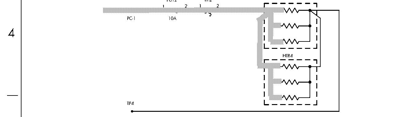
Refer to the schematic in Figure 9 - 3 on page 9 - 12. (The electrical schematic legend is on page 9-2.)
The following voltage points are measured with respect to TP4 (B-):
1. Turning the key switch (S1) on supplies battery voltage from S1 - 2 to JPC 1 1 - 1 (B+ KEY).
2. Battery voltage is at the following points on the carriage manager:
JPC 1 1 - 2 through S2 1 to JPC 1 1 - 3 (B+ ESTOP)
JPC9-4 (B+KEY)to JFT10-4 on the steer/tractor manager
JPC9-3 (B+ ESTOP) to JPT10-3 on the steer/tractor manager (closing relay K1)
3. Battery voltage is at the following points on the steer/tractor manager:
JPT11-10 (B+ KEY) to the traction power amplifier J 1 -16
4. Battery voltage is at the following points on the steer/tractor manager as B+ ESTOP:
JPT12-2 1 through the load-holding solenoid coil to JPT12-9
JPT12-21 through the lift/lower solenoid coil to JPT12-8
JPT12-2 1 through the PC contactor coil to JPT12-20
JPT12-21 through the brake coil to JPT12-17
5. The steer/tractor manager receives battery voltage and produces the following voltages:
+12volts (12VP)
+5 volts
Boost for steer power head
6. + 12 volts (12VP) is present at the following points on the steer/tractor manager:
JPT5-2 (height 120"/150 " switch S29)
JPT5-5 (height 180 " switch S25)
JFT5-8 (optional lift limit switch S24)
JPT7-2 (spare switch input)
JPT3-2 (steer home sensor S8)
JFT12-6 (optional hour meter)
JPT9-6 (to carriage manager)
JPT1-9 (MULTI connector)
JFT8-8 (steer power head)
7. + 1 1.3 volts is supplied by the carriage manager to the following points on the carriage manager (this is generated from + 12VP from the steer/tractor manager):
JPC3 - 6 (optional lower limit S60)
JPC 12 - 6 (optional sidegate switch 1, S19)
JPC7 - 2 (Deadman 1 S2)
JPC7 - 5 (Deadman 2 S23)
JPC7-8 (24 " limit switch S6)
JPC7-1 1 (60 " height switch S7)
JPC 12 - 15 (optional sidegate switch 2, S20)
JPC 1 -1 (operator display)
8. +5 volts is present at JPC2 - 3 (steer encoder) on the carriage manager.
9. +5 volts is present at PT6-3 steer feedback encoder) on the steer/tractor manager.
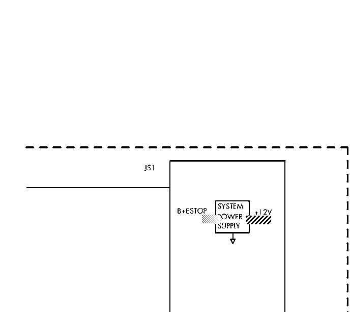
With the wire guidance option, the guidance manager receives:
1. Battery positive at JPS2-1 1 as B+ESTOP. This is also used by the power supply on the guidance manager (GM) to generate +12 volts which is used by the steer
Key Switch (S1) On
controller micro processor, internal If a problem is detected, the steer/tractor circuitry, and the filter card. The + 12 volts manager prevents truck operation and tells the is also supplied to: CM to display a corresponding fault code on the Tractor sensor at JPW2- 15 operator display.
Load sensor at JPW1 -1 5
Speed encoder at JPS1-19
2. Battery negative at JPS2 - 24.
3. Battery negative at JPS4-3 as DGND.
When the key switch is first turned on, the Microprocessor's perform a self-diagnostics of certain inputs and outputs.
The carriage manager checks:
1. The + 12 volt supply from the steer/tractor manager.
2. Checks to make sure the steer tiller encoder is plugged in.
3. Checks the state of Deadman 1 and informs the STM.
4. Checks the voltage from the travel and lift pot and sends the voltages to the STM.
The steer tractor manager checks:
1. The + 12 volt supply.
2. The voltages from the travel and lift pot and compares them to the learned neutral and out of range values.
3. The state of the P contactor at JPT12-3.
4. The state of the mast switches.
5. The state of the EPO switch at JPT10-3.
6. The state of the Deadman switches.
7. The state of the PC contactor at JPT12-3.
8. Battery Voltage for proper range at B+ key.
9. Calculates BDI using B+PC.
10. Requests feedback from the Guidance Manager on the results of it's self-diagnostics.
1 1. Inputs from the TPA to verify its operation.
The Guidance Manager checks:
1. To make sure the filter card is plugged in based on a jumper on the filter card between JS1-A10 and A1 1. 00700-CL222-05,
Section 9. Theory of Operation Toyota Orderpicker Model 7BPUE 15 Service Manual
Key Switch (S1 ) On
Tracing Legend - Electrical
= B+ Circuit
= B - Circuit
= Signal
VHHHHHHHHHH~ = 12V/ 5V