
3 minute read
Section 8. Wire Guidance


Install Kit Components
Toyota Orderpicker Model 7BPUE15 Service Manual
a. 3 lockwashers (P/N 00590-0285 1 - 71) Feed the harness through the notch in the b. 3 washers (P/N 00590-03092-7 1) housing. See Figure 8- 11. , c. 3 screws (P/N 00590-46033-71)
8. Install the snap ring (P/N 00590-46047-71) on top of the bearing in the housing. See Figure 8- 11.
9. Use gasket flange sealant (Loctite Ultra Black 598) and fill the notch in the housing. See Figure 8 - 11.
10. Connect PH6 of cable assembly (P/N 00590-45863-71) to the encoder harness connector JH6, then route the harness wires along the drive motor cables. Use cable ties as necessary, but do not overtighten.
5. Install the bearing housing (P/N 00590-46054-71jon the mounting plate with four screws (P/N 00590-03113-71). See Figure 8-9.
6. Remove the snap ring from the encoder bearing (P/N 00590-46055-71). See Figure 8- 10.

11. Route the wires through the clamps on the top deck then back over and down the wiring channel to PS1 on the steer controller card. Use cable ties as necessary.
Steer Encoder Removal

1. Turn the drive unit counter clockwise to the steering mechanical stops.
2. Remove the two mounting screws securing the encoder cover to the top of the steer motor.
3. Thread a 10-32 machine screw (1.5 in.
long) into the tapped hole in the top of the encoder. Tighten the screw against the shaft and continue to tighten until the encoder is lifted from the shaft.
Install Kit Components
Installation
1. Clean the encoder shaft. Apply retaining compound (Loctite 609)to the encoder shaft.
2. Install the steer encoder kit (P/N 00590-45880-71) on the shaft.
3. Install the encoder cover and the two mounting screws.
4. Secure the encoder to the motor with the two screws provided with the steer encoder. See Figure 8- 13.


5. Route the cable from the encoder down the side of the motor and connect to cable JH7.
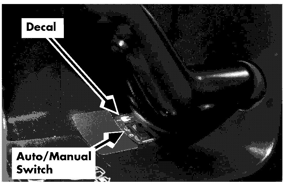
Auto/Manual Switch
1. Remove the operator console cover.
2. Remove the bezel.
3. From the backside of the bezel, use a hot knife to cut out the detent for the auto/manual switch. See Figure 8-14.
4. Place the rocker switch orange-side-up in the bezel.
5. Install the connector housing (P/N 1-0 12-339/004)on the auto/manual switch cable (P/N 00590-45865-71). See Figure 8- 1 5.
6. Connect the cable to the auto/manual switch. See Figure 8-15.Then connect to the carriage manager.

Set-Up Procedure
6. From the main menu, type s for Set Configurable Items at the prompt. Make sure the settings are correct for the NOTE: If you are setting up a truck with guidance application. Change settings if factory-installed wire guidance, skip to necessary. ste~4.
Set-Up Procedure
NOTE: To change these settings:
1. Install the wire guidance kit components. See " Install Kit Components " on page 8 - 3. Use the up and down arrows to select
2. If necessarv, flash the latest version of the options. software through Flashware. See " Flash Use the left arrow to decrease values, Memory Program" on page 10 - 6. and the right arrow to increase values.
3. Turn on the wire guidance option in
7. After changing the truck configuration: Flashware. See " Enable Wire Guidance in Truck restarts automatically FlashWare" on page 8 - 9. Horn beeps when self-diagnostics is
4. Perform the Guidance Parameter Setup to finished set the distance from wire and heading angle ~arameters.See " Guidance - L Parameter Setup " on page 8 - 9.
5. Learn the guide wire frequency. See "Learn Guide Wire Frequency" on page 8 - 10.
6. Learn the guide wire offsets. See "Learn
Screen returns to the main menu
8. Type x to exit FlashWare.
Guidance Parameter Setup
1. Connect the FlashWare program to the Wire Guidance Offsets" on page 8- 10. truck.
7. Perform the Guidance Check to make sure
2. Make sure the Wire Guidance Option is the truck can steer on the wire properly. turned on in FlashWare. See " Enable Wire See " Guidance Check" on page 8- 11. Guidance in FlashWare" on page 8 - 9.
Enable Wire Guidance in FlashWare
NOTE: For complete instructions on FlashWare,
3. At the prompt on the Main Menu, type s for Setup Configuration Items and press Enter key.
4. Set the following parameters in the Truck See "Software Configuration" on Configure Menu. page 10 - 1.
1. Make sure the latest version of FlashWare is installed in the truck. If not, flash load the latest version. See " Flash Memory Program" on page 10 - 6.
2. From the main menu, type o for Options at the prompt.
Distance From Wire Slow
Distance From Wire Stop
Heading Angle Slow
Heading Angle Stop
3. From the options menu, use your arrow NOTE: If wire guidance is turned off in keys to move to the Wire Guidance prompt Flashware, the Truck Configure Menu and press the enter key. will display the lift cutout threshold
4. In the box that appears on the left, type in only. the 4-digit authorization code you
5. Type x to save these parameters and exit obtained from the Toyota Parts this menu. Distribution Center.
5. Type y at the Wire Guidance prompt, and follow the instructions at the bottom of the screen.


