
5 minute read
Toyota Orderpicker Model 7BPUE 15 Service Manual


Section 7. Component Procedures
Control Handle
spring with the tangs straddling the pot pull the travel pot/bracket assembly from bracket pin. See Figure 7 -16. the enclosure. See Figures 7 - 23 and 7 - 24.
NOTE: Replace the spring if the tangs are not parallel. Do not bend the spring.
8. Install the two remaining fiber washers.
9. Install the lift/lower knob. See "Lift/Lower Knob Installation/Adjustment" on page 7 - 21.

Travel Pot (VR 1 )
Disassembly
1. Remove the four hex head cap screws from Figure
Screws the front of the travel pot enclosure and remove cover. See Figure 7 - 22.
Remove screws
3. Loosen the set screw on the gear two full turns and slide the gear off the shaft. See -
2. Remove the two pan head machine screws Figure 7 - 25. from the back of the enclosure. Carefully
4. Remove retaining nut and lock washer from pot and separate from the bracket. See Figure 7 - 25.

5. Carefully remove heat shrink tubing from the terminals and identify the wires so they can be installed in the same location on the new pot.

Control Handle
6. Carefully unsolder the harness wires.
Assembly
1. Slide 3/8 in. (9.5 mm) long shrink sleeving over previously sleeved wires.
2. Solder all electrical components to the harness. See "Hand Soldering Procedures " on page 7 - 22.
3. Shrink sleeving as necessary.
4. Assemble pot and bracket and install retaining nut and lock washer. When installing the travel pot into the bracket, leave the mounting nut finger tight. See Figure 7 - 25.
5. Install the gear on the pot shaft, aligning the set screw with the flat portion of the shaft.
6. Install the travel pot/bracket assembly into the enclosure. Engage the travel pot gear with the shaft gear (there is one large tooth that is used to align the gears). Tighten the pot gear set screw and torque to 3 to 4 in. lb. (0.3 to 0.4 N*m).
Acaution
It is very easy to over-torque and ruin the gear.
7. Tighten the two pan head machine screws on the back of the enclosure while moving the handle to ensure there is no binding. See Figure 7 - 23.
8. Install the handle in the truck.
9. Adjust the travel pot to the correct voltage values.
10. Tighten the retaining nut.
11. Install the cover on the travel pot enclosure with the four hex head cap screws. See Figure 7 - 22.
Travel Spring and Pinion Disassembly
1. Remove the four hex head cap screws from the front of the travel pot enclosure and remove cover. See Figure 7 - 22.
2. Use a pin removal tool and pull pins 3 thru 6 from JC - 9. These wires pass through the shaft to the lift/lower pot and horn switch.
NOTE: The washer and shims can easily slip off of the shaft gear. Observe the proper position of these components before disassembling them.
3. Remove the button head screw from the shaft gear and slide shaft out of enclosure. See Figure 7 - 24.
4. Carefully rotate the shaft gear assembly to disengage the spring tangs from the pin. Remove the shaft gear assembly from the enclosure.
Assembly
1. Slide the shaft gear assembly back into enclosure. Engage the travel pot gear with the shaft gear (there is one large tooth that is used to align the gears).
a. Make sure the spring tangs straddle the pin (tangs should be parallel). If the spirol pins were replaced, make sure they are installed such that when the spring is installed, the spring sits on an even edge of the pin and not on the gap.
NOTE: Replace the spring if the tangs are not parallel. Do not bend the spring.
b. Make sure the washer and shims are properly aligned to allow the handle shaft to slide easily through the enclosure. See Figure 7 - 26.

2. Route the lift/lower pot and horn wires through the enclosure. Carefully slide the shaft through the enclosure, passing through the shaft gear assembly, washer, and shims.
3. Align the screw hole in the handle shaft with the hole in the shaft gear. Apply thread locking compound (Loctite #425) to the threads in the shaft and on the button head screw. Install the screw and torque to 8 to 12 in. lb. (0.9 to 1.3 N*m).
4. Reinstall the wire pins into the connector.
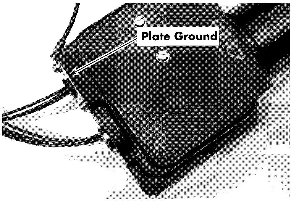
5. Inspect the tab on the plate ground to ensure that it is in contact with the bronze handle shaft bushing. See Figure 7 - 27.
Control Handle
4. Check the potentiometer for proper operation and spring return to neutral. Correct any binding.
5. Install and tighten two nylon set screws on top of the metal set screws.
6. Verify the potentiometer reference voltages.
Cleaning and Inspection
Acaution
When cleaning plastic parts, use a dry rag or a cleaner that is safe on plastics. Most chemicals can damage plastic.
While performing a repair on the Control Handle, clean and inspect the parts listed in Table 7 -1.
Table 7- 1 : Control Handle Checks Part
I
Horn button assembly (button, pin, & spring)
Lift/lower pot bracket
Travel pot
6. Install the cover on the travel pot enclosure with the four hex head cap screws. See Figure 7 - 22.
Lif t/Lower Knob Installation/Adjustment
1. Rotate the lift/lower potentiometer shaft fully counterclockwise.
2. Install the lift knob on the potentiometer shaft. The pin on the knob must fit between the tangs of the potentiometer return spring.
3. Rotate the lift/lower knob fully counterclockwise and tighten the metal set screws to 6 to 8 in. lb. (0.7 to 0.9 N*m).
Cheek for:
Cracks or deformation
Cracks, deformation, loose dowel pin, over round or oversized shaft hole
Cracks, gear deformation, stripped threads
Cracks, gear deformation or loose spirol pin rTravel pot enclosure
Travel shaft gear assembly Handle halves
~/,'"wer
Plate ground
Other hardware
Cracks, loose spirol pin, stripped threads, deformation or indents on external stops
Cracks, damage or deformation/indents on external stops
Cracks, deformation, stripped threads, loose dowel pin
Check for continuity between the control handle shaft and the truck frame
Stripped threads. All screw threads should be cleaned.
Control Handle
Hand Soldering Procedures
When hand soldering is performed on solid state potentiometers, the following is recommended:
Flux - rosin base
Solder - 60/40 rosin core or equivalent
Solder Iron - 55 watt max.
TipSize - 0.118 in. (3mm) dia. x 1.182in. (30 mm) long screwdriver
Tip Temperature - 500°F (260°C) max.
Terminal Contact Time - 6 seconds max.
NOTE: Apply light soldering iron pressure on the terminal. Make sure the tip is clean. A dirty tip does not transfer heat well, therefore requiring longer dwell time and greater tip pressure.
Acaution
Contact contamination can occur if cleaning solvent is allowed to enter switches or potentiometers.
After soldering, clean terminals with a brush dampened with an alcohol - based cleaner. Make sure cleaner does not seep into the electrical component.
NOTE: Components damaged due to solvent saturation will not be covered under warranty.
Installation
1. Install control handle on truck. Connect JPC9.
2. Reconnect the battery connector and turn the key switch ON.
3. Perform LEARN and test truck operation before returning to service.


