
3 minute read
Toyota Orderpicker Model 7BPUE15 Service Manual


Section 7. Component Procedures
Hydraulic Components Lift Pressure Relief Valve Adjustment
Lift Pressure Relief Valve
Adjustment
1. Install a calibrated pressure gauge [3000 psi (20,682 kPa) at mid - range] in the lift pressure test port (Gl).See Figure 7 - 94.
2. Loosen the locknut on the lift pressure relief valve (RV1) to back out the high - pressure relief.
3. Make sure emergency lower valve is closed.
4. Place a maximum rated load + 200 lb. (90.7 kg.) on the forks.
5. Start the lift system and turn the pressure relief screw clockwise until the platform starts to lift. Note the pressure required when the platform starts to elevate. On three - stage trucks, continue lifting until the third stage of the mast starts lifting. Record the pressure reading.
6. Lower the operator platform and remove the load.
7. Chain the mast sections together and lift or lift the operator platform until the upper limit is reached.
8. To adjust pressure: a. Continue trying to elevate, and turn lift pressure adjusting screw (at RV1) to obtain a pressure reading of 100 to 300 psi (689 to 2068 kPa) greater than that required to lift maximum rated load (value recorded earlier). b. TO increase pressure, turn adjusting screw clockwise. To decrease pressure, turn adjusting screw counterclockwise. c. Tighten locknut on lift pressure relief valve.
9. Check pressure again. If value has changed, repeat this procedure until the correct pressure reading is obtained.
10. Turn key switch OFF.
1 1. Disconnect pressure gauge and reinstall cap on lift pressure test port (Gl).
Bleeding the Hydraulic System
Bleeding the Hydraulic
System
H y draulic Components
4. Repeat cylinder.the steps for the other side
5. Connect battery and turn key switch ON.
6. Lower operator platform all way down to floor.
7. Fully lift and lower platform several times.
8. Clean up any spilled hydraulic fluid.
9. Check hydraulic reservoir level and fill as necessary. See "Lubrication Specification Chart" on page A - 2.
Center Cylinder
If the truck has a three - stage mast, it will have a center cylinder. To bleed the center cylinder:
1. Elevate the operator's platform enough to extend the center cylinder approx. 3 in. (76 mm).
2. Loosen, do not remove, the bleed screw. (Use 3 mm Allen wrench for center You must bleed the hydraulic system to remove cylinder.) Hold rag beneath the bleed screw any trapped air whenever you: to keep hydraulic fluid from spraying out. Change a hydraulic line

- - -
3. When only hydraulic fluid starts flowing from the cylinder, securely tighten the Remove a hydraulic cylinder bleed screw.
Disconnect a hydraulic fitting
Remove the hydraulic pump
Notice that the load is bouncing
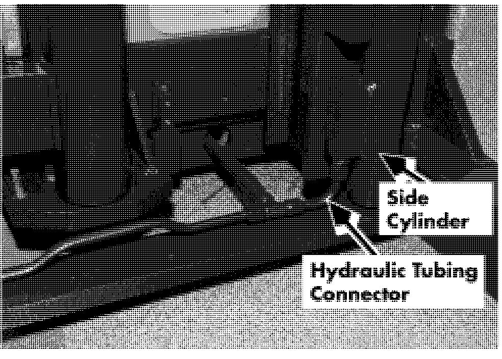
Side Cylinder
1. Extend the cylinder then turn the key switch OFF and disconnect the battery.
2. Loosen, do not remove, the bleed screw. (Use 3 mm Allen wrench for side cylinders.) Hold rag beneath the bleed screw to keep hydraulic fluid from spraying out.
Acaution
The bleed screw should only be loosened enough to allow the air to escape.
3. When only hydraulic fluid starts flowing from the cylinder, securely tighten the bleed screw.
Toyota Orderpicker Model 7BPUE15 Service Manual
Hydraulic Components
Side Cylinder
Section 7. Component Procedures
Side Cylinder
4. Remove the bolt in the top of the lift cylinder that connects it to the bracket on the mast.
5. Elevate the platform until it clears the ram assembly enough to allow removal
6. Block the carriage and mast. jacked up. Never block the truck
Use extreme care whenever the truck is
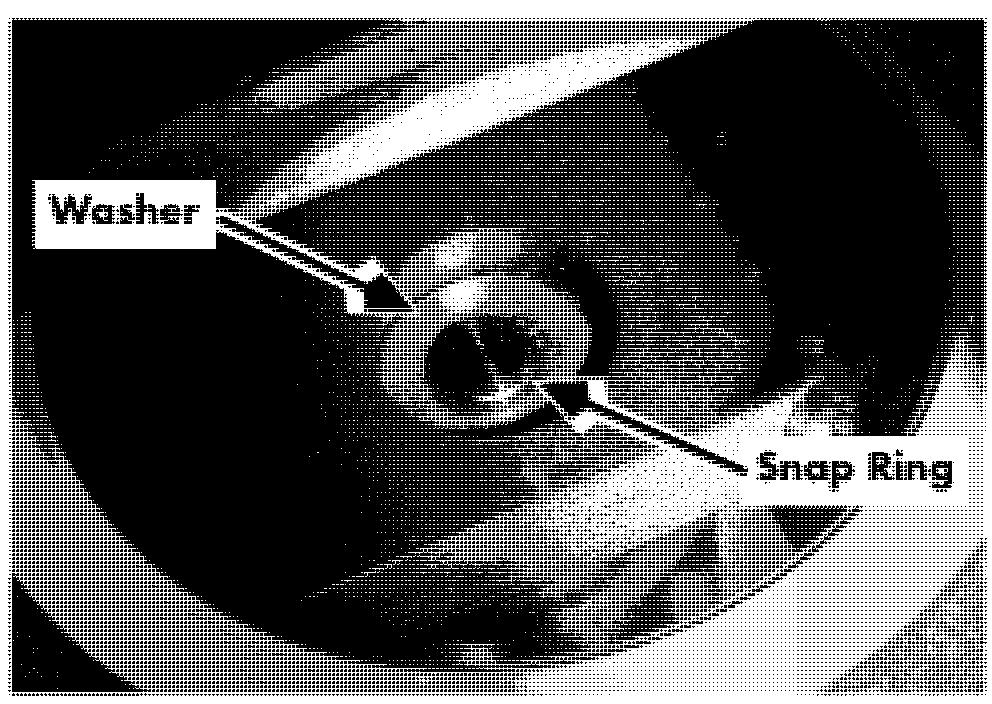
7. Remove the snap ring from the bottom of between the mast and the floor. Keep the cylinder. See Figure 7 - 97. hands and feet clear from vehicle while jacking the truck. After the truck is jacked, place solid blocks beneath it to support it. DO NOT rely on the jack alone to support the truck. See "Jacking Safety" on page 2- 1 1.
NOTE: Using a mirror will enable you to see the snap ring at the bottom of each cylinder housing in the following procedures.
Remove
1. Elevate the platform far enough to access the tubing that connects to the bottom of the lift cylinder but not far enough to extend the side cylinder. Block the carriage in place.

8. Remove the bolt that attaches the cylinder
2. Remove the tubing from the bottom block housing to the main frame of the truck. on the cylinder that is to be removed and See Figure 7 - 98. cap both the tubing and the fitting to the lift cylinder.
9.


