
3 minute read
Section 7. Component Procedures Toyota Orderpicker Model 7BPUE15 Service Manual


Motors (General)
Electrical Components
2. Check brush spring tension. See "Motor schedule to obtain the maximum efficiency Brush Spring Tension " on page 7 - 37. from the electrical equipment.
Set up and rigidly adhere to a strict inspection
3. Clean brushes and holders. Wipe the commutator with a dry, lint-free cloth. DO NOT USE lubricants of any kind on or around the commutator.
4. Check brush holders for solid connection to the mounting support. Tighten the mounting screws as necessary.
5. Check the cap screws holding the brush cross connectors to the brush holder body.
Each partial inspection of the motor should include the following:
1. Inspect the brushes for wear and for proper contact with the commutator. Record the level of wear on the brushes. This history will give you an indication of whether a brush should be changed or if it can wait until the next inspection. Refer to Page 7 - 37 for acceptable brush length and Figure general motor information. -

NOTE: Overloading a unit is ultimately reflected
6. Make sure the motor terminals are in the motor and brush wear; therefore, secured tightly to the motor frame. Be you must take this into account when careful not to strip the threads or crush considering brush replacement. the insulating parts. See "Terminal Nuts" on page 7-38.

7. Check all the cap screws around the frame for tightness.
8. Keep the outside frame of the motor clean and free from dirt. Maintain a free air passage around the motor to permit heat radiation.
Replacement
If one brush needs replacement, always replace the entire set of brushes.
Use only genuine Toyota brushes. Using another type of brush could damage the commutator or cause excessive brush wear and will void your warranty.
Electrical Components
If the end of the brush is not already contoured to fit the commutator:
NOTE: Form the brush contour using a brush seating stone. Spring Scale
- Rotation \
Pull paper in direction of rotation
Motors (General)
Motor Brush Spring Tension Inspection
1. Turn the key switch OFF and disconnect the battery connector.
2. Remove the tractor cover.
3. Slide the brush up slightly in its holder.
4. Insert a paper strip between the brush face and the commutator.
5. Place a small leather loop around the coil spring for the brush. If the brush spring has a loop at the brush, hook the spring scale directly to the spring.
6. Attach a 5 lb. (2.27 kilogram) spring scale to the leather loop.

7. While gently pulling the scale outward, slowly pull the paper strip in the direction that the commutator normally rotates.
8. When the paper strip begins to move freely, the spring scale will read the spring brush tension.
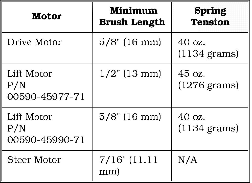
9. Refer to the table below for proper spring tension:
10. Repeat steps 3 through 9 for the remaining brushes.
Section 7. Component Procedures

Motors (General)
Commutator
Toyota Orderpicker Model 7BPUE15 Service Manual
Electrical Components terminal securing nut to avoid twisting the stud.
Securing Nut
The commutator should be inspected for surface condition and high mica.
The commutator must be smooth and clean to provide maximum brush wear. When commutators are not properly maintained, carbon dust can collect in the grooves between the segments. This can lead to a short circuit in the armature.
Good commutation will be indicated by a dark-brown, polished commutator and an evenly polished brush wearing surface.
If the commutator appears rough, pitted, or has signs of burning or heavy arcing between the commutator bars, the motor should be removed for servicing.
Terminal Nuts

Whenever you disconnect and reconnect any power leads to a motor, always tighten the motor cable securing nuts with a torque wrench to prevent over-tightening them and damaging the motor. Use a second wrench on the stud
Securing Nut
Stud terminal securing nuts should be torqued to 140-160 in. lbs. (15.8-18.1 Nm) and motor cable securing nuts to 100- 120 in. lbs. (11.2-13.6 Nm). Check these torques each time you check motor brushes.
Two different methods are used to connect power leads on this truck. The double nut method is shown in Figure 7 - 51. The triple nut method is shown in Figure 7-52. The torques listed in the paragraph above apply to both methods.

Toyota Orderpicker Model 7BPUE 15 Service Manual
Electrical Components
Drive Motor
Removal
Section 7. Component Procedures
Drive Motor
9. Break seal between drive motor flange and drive unit. Use 2 screws from steer motor mounting plate. See Figure 7 - 54.


10. Attach a suitable hoist to drive motor and
1. Remove tractor covers. See " Tractor lift motor out of truck. Covers" on page 7 -11.
2. Turn drive unit using steering wheel so installation you can reach power cables.
11. Clean sealant from motor flange and cap
3. Turn key switch OFF and disconnect screws for drive motor. See Figure 7 - 55. batterv.
4. Remove brake from drive motor (if the motor is to be replaced). See "Brake" on page 7 - 27.
5. Disconnect power cables from drive motor. Note location for installation and label if necessary.
6. Remove steer motor. See "Steer Motor" on page 7 - 42.
7. Remove dipstick and plug. See Figure 7 - 53.
8. Remove the bracket that activates the home prox switch.


