
1 minute read
Section 9. Theory of Operation Toyota Orderpicker Model 7BPUE 15 Service Manual


input to the STM. The STM determines the request for lift or lower and speed based on the learn values stored in the STM. Second speed shift or lower is activated at about 50% of the stroke on the pot.
Input from the S3 horn switch.
B- for the horn switch.
Input from the optional lift lower limit bypass switch, S5 1
Not connected to any circuitry on the CM.
Not connected to any circuitry on the CM.
B- for the optional lift/lower limit bypass switch.
Positive supply from the STM power supply for S2 Deadman 1 switch.
Input from the S2 Deadman 1 switch.
6- to the S2 Deadman 1 switch.
Positive supply from the STM power supply for the S23 Deadman 2 switch.
Input from the S23 Deadman 2 switch.
B- to the S23 Deadman 2 switch.
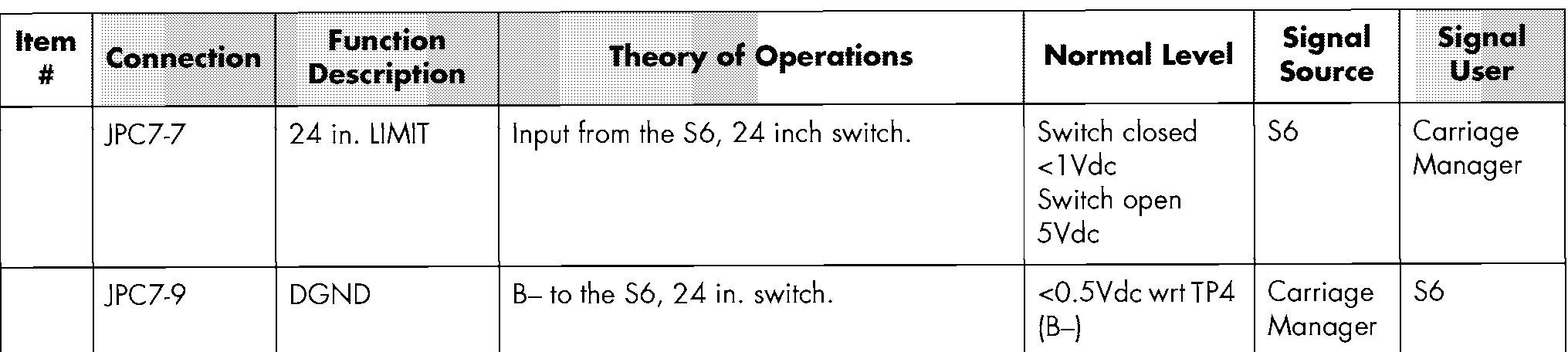
Positive supply from the STM power supply for the S6, 24 inch switch.
JPC7-11
Positive supply from the STM power supply for the S7 switch, 60 in. switch.
Input from the 60 inch switch, S7.
B- to the 60 in. switch, S7.
Positive supply from the STM power supply for the optional S19 Sidegate 1 switch.
Input from the S19 Sidegate 1 switch (optional).
JPC1 2-8
JPC12-15 JPCl2 - 16 JPCl2 - 14 JPCl2 - 17
B- to the optional S19 switch.
Positive supply from the STM power supply for the optional S20 Sidegate 2 switch.
Input from the S20 Sidegate 2 switch (optional).
B- to the optional S20, Sidegate 2 switch.
Not connected to any circuitry on the CM.
Not used for anything.
B+ supply for the optional lift/lower alarm.
Path for the Carriage Manager to supply B- to the lift lower alarm. There will be B+ measured here with no command to activate the alarm and it will drop to OV when the CM takes it to B-


