
7 minute read
Section


Fuses
Fuses
Replacement
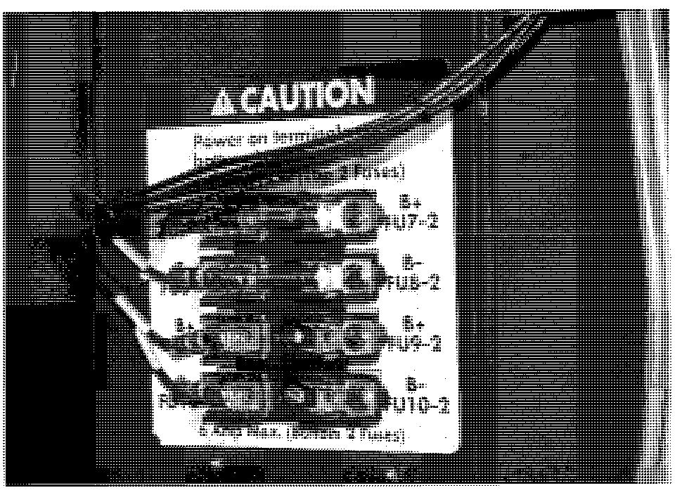
When replacing fuses, make sure fuses are installed in the proper order. See Figure 7 - 76.
Electrical Components
Auxiliary Power Fuses

Installation
1. Turn key switch OFF and disconnect battery.
2. Remove operator console cover.
3. Remove the front plate under the console from the operator platform.
4. Line up the fuse block on decal and mark top and bottom holes.
5. Punch out the holes.
6. Push the fuse block mounting screws through the holes in the decal.
7. Line up the screws with the mounting holes on the plate and adhere the decal to the plate.
8. Mount the fuse holder on the caution decal. Secure with two pan head screws. See Figure 7-79.

Electrical Components
9. Mount the fuse holder plate with two thread - forming screws to the inside of the platform upright. See Figure 7 - 79.
10. Install follows:
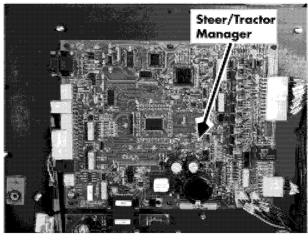
11. Route the harnesses through the raceways between the fuse holder and the carriage manager.
12. Connect wires to fuses as marked on sleeves. Connect to carriage manager at JPC 10.
13. Install the fuse cover using the flat washer and screw.
14. Install operator console cover.
15. Install front plate on operator platform.
Circuit Cards (General) Electrical Components
Circuit Cards (General)
2. Remove appropriate cover(s). See "Tractor Covers" on page 7- 1 1.
3. If removing a circuit card from tractor,remove circuit card cover.
4. Disconnect all connectors on this circuit card.
5. Remove all screws holding circuit card to frame.
Acaution
Use proper precautions against electrostatic discharge. See "Static Safety" on page 2-9.

NOTE: Before removing a good carriage
Installation
1. Install new circuit card with the screws you removed earlier.

2. Attach connectors to circuit card.
3. Connect battery connector and turn key switch ON.
4. If installing a circuit card in the tractor, install circuit card cover.
5. Install appropriate cover(s).
6. Connect power and test operation before manager, use the Flashware Program to returning truck to service. clear the memory. See "Clear Primary Memory" on page 10 - 6.
Removal
1. Turn key switch OFF and disconnect battery.
Electrical Components Switches (General)
Refer to the electrical schematic in the Appendix to identify the electrical circuit location of the switch.
Deadman Switches
There are two deadman switches (S2 and S23).
Replacement
Use extreme care whenever the truck is jacked up. Keep hands and feet clear from the vehicle while jacking the truck. After the truck is jacked, place solid blocks beneath it to support it. DO NOT rely on the jack alone to support the truck. See "Jacking Safety" on page 2-1 1.
Switches (General)
5. While holding the two return springs in place, lift pedal straight up.
6. Remove the two screws mounting the deadman switch to bracket.
7. Disconnect wires from switch(es). Note location and mark if necessary for recondition later.
8. Replace defective switch(es). See Figure 7 - 83.

9. Reconnect wires.
10. Align washers with holes.
11. While holding the two return springs in place, install pedal assembly. See Figure 7 - 83.
12. Install washer and lock nut on bottom of deadman pedal post.
13. Connect power and test truck operation before returning to service.
Emergency Power Off Switch
The emergency power off (EPO) switch is S2 1.
Removal
1. Disconnect battery, turn key switch OFF and remove key.
2. Remove operator console cover. See " Operator Console Cover" on page 7 -12.
3. Disconnect wires EPO 1 and 2 from back of EPO switch. See Figure 7 - 84.

1. Raise operator platform high enough (at least 3 feet [91.44 cm]) to access bottom of deadman pedal from under platform.
2. Block operator platform with a 4 in. x 4 in. (100 x 100 mm) block.
3. Turn key switch OFF and disconnect battery connector.
Switches (General)
4. Loosen two screws on backside of EPO
Electrical Components
4. Reconnect battery connector and check switch. operation.
5. Hold lower half of switch, push in and
5. Turn key switch OFF and disconnect rotate top half 90" counterclockwise to battery connector. unlock halves of EPO switch.
NOTE: The switch may turn hard.
6. Install operator console cover.
7. Connect battery and test operation before
6. Lift top half of EPO switch from bezel. returning truck to service.
Installation
1. Insert lower portion of EPO switch in its hole in bezel.
2. Slide upper half of EPO switch over lower half until it is seated. Rotate top half 90" clockwise to lock.
3. Tighten screws on backside of EPO switch. See Figure 7 - 84.
4. Reconnect wires to back of the EPO switch.
5. Install operator console cover.
6. Connect power and test truck operation before returning truck to service.
Key Switch
This lift truck is equipped with a two position (off/on) key switch (S1), which energizes all truck operations.
Removal
1. Turn key switch OFF and disconnect battery connector.
2. Remove operator console cover.
3. Remove mounting nut from stem of key switch. See Figure 7 - 84.
4. Remove key switch.
5. Disconnect wires from bottom of key switch.
Installation
1. Connect wires to terminals.
2. Install new key switch and tighten locking nut.
3. Secure mounting nut on key switch stem.
Electrical Components
Warning Light
Replace
1. Turn key switch OFF and disconnect battery.
2. Unplug warning light harness. See Figure 7-85.

3. Cut cable ties.
4. Remove foam gasket and light.
5. Install new light and foam gasket.
6. Connect harness.
7. Connect power and test function of warning light before returning truck to service.
Warning Light
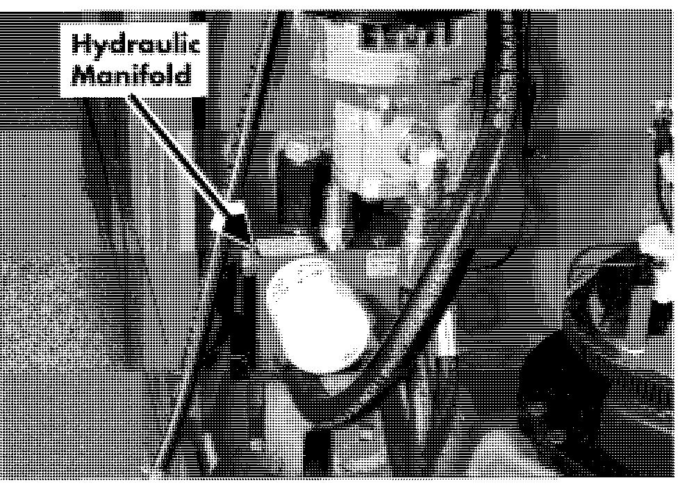
Hydraulic Manifold
Acaution
Lower the operator platform before removing the hydraulic manifold.
Remove
1. Turn key switch OFF and disconnect battery.
2. Remove tractor covers.
3. Drain hydraulic reservoir. See "Hydraulic Fluid" on page 7-60.
4. Remove hoses.
5. Remove the two bolts holding the manifold to the bracket.
Install
1. Mount manifold to its bracket.
2. Replace the O - rings at manifold openings.
NOTE: Lubricate O-rings with clean hydraulic fluid before installing.
3. Connect the hoses to the manifold.
4. Fill reservoir. See "Lubrication Specification Chart" on page A-2.
5. Install tractor covers.
6. Connect power and test lift system function before returning truck to service.
Hydraulic Components
Hydraulic Reservoir Remove
1. Turn the key switch to OFF and disconnect battery.
2. Remove top and tractor covers.
3. Drain the hydraulic fluid. See "Hydraulic Fluid" on page 7-60.
4. Disconnect the warning light and hour meter wires.

5. Install tube weldment.
Hydraulic Reservoir
6. Install strainer and filler breather cap. See Figure 7-87.
NOTE: To help prevent the hoses from slipping off the protrusions on the reservoir:
Clean and dry the hoses and protrusions
Make a rough surface on the protrusions
7. Attach hoses. Tighten the clamp as close as possible to the top of the hose.
5. Remove the filler breather cap and strainer from the top of reservoir. See Figure 7-87.
6. Remove the six screws that hold the return line bracket to the reservoir.
7. Remove the tube weldment. See Figure 7-87.
8. Remove the bracket located behind the drain and suction hoses.
9. Slide the reservoir out of the tractor. Install
1. Fit the grommet and protrusion in the bottom of the tank and install the bracket that holds the suction and drain hoses.
2. Slide the new tank in place in tractor.
3. Install the bracket behind the drain and suction hoses.
4. Lubricate O-ring with clean hydraulic fluid and install.
Hydraulic Fluid Hydraulic Components
Hydraulic Fluid Replace
1. Lower carriage to floor to relieve hydraulic pressure.
2. Turn key switch OFF and disconnect battery.
3. Remove the tractor covers.
NOTE: In the next steps you will need a 5 gallon b. Drain hydraulic fluid. See Figure 7-89.
5. Insert drain plug in drain hose and fill the hydraulic reservoir with new fluid. See "Lubrication Specification Chart" on page A-2.
6. Connect power and test lift functions before returning truck to service.
7. Install tractor covers.
Cold Storage Hydraulic Fluid (19
liter) capacity container.
4. Drain the hydraulic reservoir.
a. Remove the drain plug from the drain
Replace
1. Drain the hydraulic reservoir. hose. See Figure 7-88.

2. Open the bleed screws on all lift cylinders. See "Bleeding the Hydraulic System" on page 7-64.
3. Drain the return hose (from the reservoir to the manifold).
4. Open the emergency lower valve. See Figure 7-88.

5. Drain the inlet hose (pump to reservoir).
6. Drain the outlet hose (to cylinders).
7. Drain the hose from the pump to the manifold.
8. Change the filter on the manifold.
Hydraulic Components
Solenoid Valves Solenoid Valves
Emergency Lowering Knob
This knob allows you to lower the carriage without using the lower switch.
1. Turn the emergency lower knob 1 SO0 counterclockwise. See Figure 7-9 1.

2. Allow the carriage to lower.
3. After the carriage is lowered to floor, push in knob and turn 180" clockwise. Replace
1. Lower operator platform completely.
2. Turn key switch OFF and disconnect battery.
3. Disconnect wires from solenoid valve.
4. Remove nut holding coil to valve barrel and pull off coil.
5. Remove the valve barrel.
6. If valve has O - ring, lubricate O-ring with clean hydraulic fluid before installing barrel.
7. Place new valve barrel in manifold and secure. Tighten the valve until a torque value of 22 ft. lb. (30 Nm) is achieved.
8. Place the coil on the valve barrel.
9. Secure nut holding coil to valve barrel. Torque nut to 5 ft. lbs. (7 Nm).
10. Reconnect wires to solenoid.
Lift Pump and Motor H y draulic Components
Lift Pump and Motor

6. Remove and replace both hydraulic fittings on the lift pump.
Replace
1. Remove top and tractor covers.
2. Turn key switch OFF and disconnect battery.
NOTE: In the next steps you will need a 5 gallon (19 liter) capacity container.
3. Drain hydraulic fluid. See "Hydraulic Fluid" on page 7 - 60.
NOTE: Make sure hoses are disconnected from pump.
4. Remove the two mounting bolts securing the lift pump to the lift motor. See Figure 7 - 93.

5. Carefully separate the pump from the motor, taking care not to damage the toothed spline.
7. Apply molybdenum anti - seize compound (P/N 00590 - 04836 - 71) to the mating surfaces of the lift motor spline and pump.
8. Carefully mate the new lift pump spline to the lift motor and attach the lift pump to the lift motor with the two mounting bolts.
9. Replace the filter on the manifold. See Figure 7 - 92.
10. Connect hoses.
11. Insert drain plug in drain hose and fill the hydraulic reservoir with new fluid.
12. Connect power and test lift functions before returning truck to service.
13. Bleed the hydraulic system as necessary.
14. Install tractor covers.


