1 minute read
Flow Control Valve


7. Place
Replace
1. Lift and block carriage enough to reach valve housing block.
2. Turn key switch OFF and disconnect the battery.
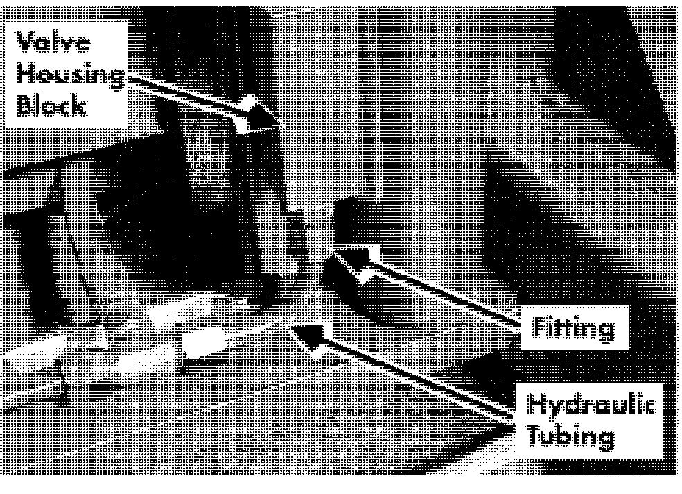
3. Remove hydraulic tubing. See Figure 7 - 108.
4. Remove fitting. See Figure 7 - 108.
5. Pull out flow control valve.
6. Place the new valve in the housing.
NOTE: Follow the directional arrow on the flow control valve to install it correctly. It should be pointing out of the housing in the direction of flow. See Figure 7 - 109.

end first and tighten. Install hydraulic tubing. Remove blocks and bleed the hydraulic system. See "Bleeding the Hydraulic System " on page 7 - 64. Connect power and test lift function befc returning truck to service.
block
Three-Stage Carriage
Do not dace hands between the masts before blocking the carriage.
6. Feed cable through carriage to tractor. jacked up. Never block the truck
Use extreme care whenever the truck is
7. Use 90" snap ring pliers to remove snap between the mast and the floor. Keep ring holding chain rocker assembly to hands and feet clear from vehicle while center cylinder. See Figure 7- 111. jacking the truck. After the truck is jacked, place solid blocks beneath it to support it. DO NOT rely on the jack alone to support the truck. See "Jacking Safety" on page 2- 1 1.

Removal
1. Turn key switch OFF and disconnect battery.
2. Remove operator console cover.
3. Remove electrical over - the - mast cable from bottom pulley on carriage. See Figure 7- 110.
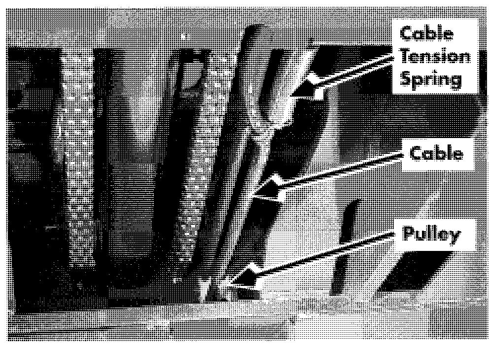
4. Disconnect cable tension spring from carriage. See Figure 7 -1 10.
Attach a suitable hoist to carriage and lift approximately 1 ft. (30.5 cm).
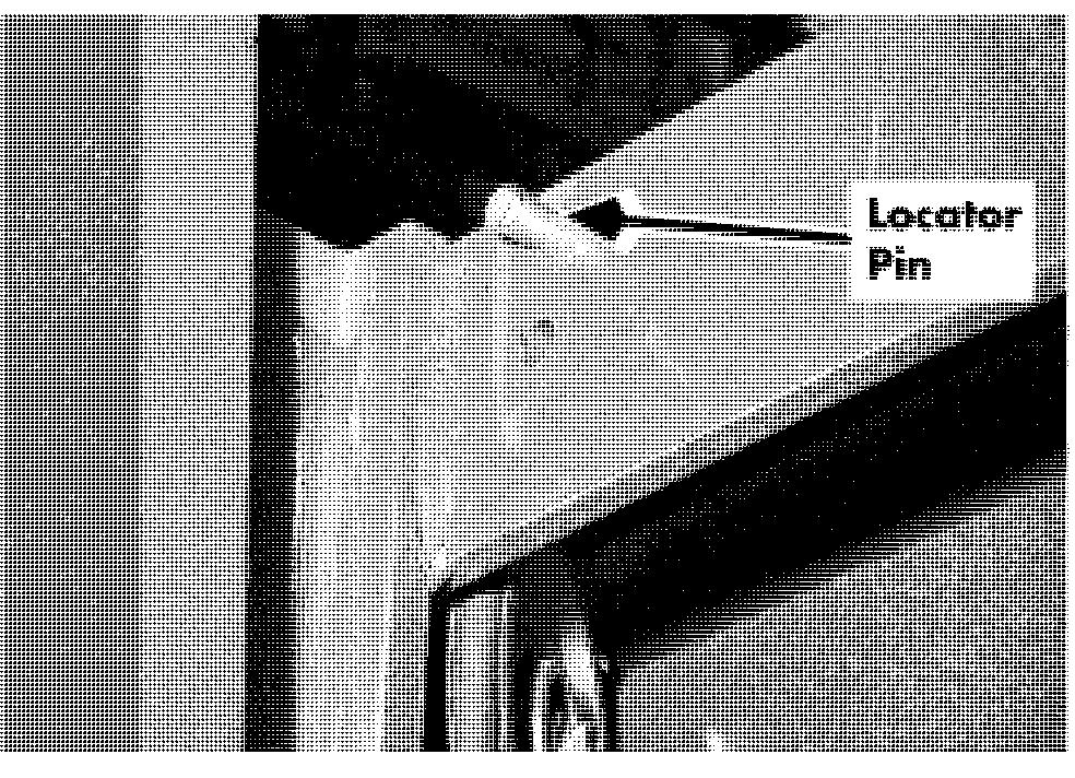
Remove rocker assembly, its associated hardware and chain from center cylinder. Place chain on operator platform. Remove end cap from center cylinder. Remove carriage stops (2) from inner mast and pound in locator pins until carriage can clear the mast. See Figure 7 -112 and Figure 7 - 1 13.
4. Position platform 3 ft. (1 m) from floor.
5. Install rocker assembly, its associated hardware and chain on center cylinder. See Figure 7- 115.

6. Install endcap pulley on center cylinder.
7. Feed chains for center cylinder and over - the - mast cable.
12. Remove operator platform.
Installation
1. With suitable hoist, lower bottom bearings on carriage into channel on inner mast.
2. Make sure there are sufficient shims to prevent side play. See "Mast Bearings" on page 7 - 85.

3. Make sure 2 switches (S6 and S7) at bottom of carriage are riding their switch rail properly. See Figure 7 - 1 14. 00700 - CL222 -
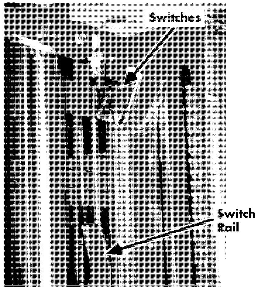
March 2005
8. Feed over - the - mast cable through back of carriage to carriage manager and connect to JPC8 and JPC9.


