3 minute read
Section 9. Theory of Operation


Travel A
Toyota Orderpicker Model 7BPUE 15 Service Manual
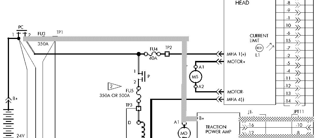
Tracing Leeend - Electrical
= B+ Circuit
= B- Circuit = Signal
VHMBMHHM = 12V/5V A
.e 9-5. Moving Speed/Directional Control (Sheet I of 4)


00700-CL222-05, 1 5 March 2005


Steering Steering
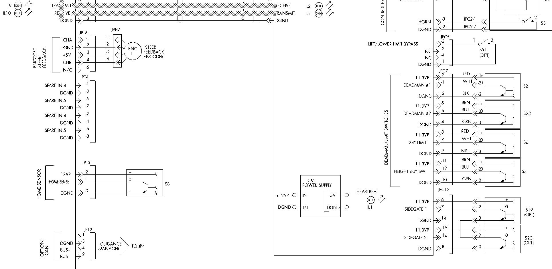
The Steering Encoder is located on the operator's carriage, behind the steering wheel.
When the battery is connected, the key switch is ON and the deadman pedal is down, the following events occur when the operator turns the steering wheel in either direction:
The steering encoder sends a quadrature - phase output to the CM when the steering wheel is turned. As the steering wheel is turned, two individual square waves are produced (CHA and CHB). The relationship between these two square waves tells the CM which way the steering wheel is turning. The number of pulses generated tells it of how far and how fast the steering wheel has been turned. The degree of rotation of the drive unit is not in direct correlation to the distance the steering wheel is turned. Once the steering wheel stops turning, the drive unit stops turning. Determining which way the steering wheel is turned is based on which one of the two square waves is ahead of the other. The one that is ahead tells which way the wheel is turning. See Figure 9-6.
CHANNEL A leads
CHANNEL B by
LEFC TURN angle 0 CHANNEL B


CHANNEL A lags
CHANNEL B by angle 0
These square waves are read by the CM. The CM sends this information over the transmit line to the STM.

The STM sends voltages to the steer power head to activate the steer motor. STEER DIR 1 and STEER DIR 1 PWM turn on the transistors required to turn in one direction. The STEER DIR 2 inputs will turn it the other direction.
The BOOST + and BOOST - inputs are required for both steering directions. BOOST + is used to power on set of transistors for steering and Boost - is used for the reference by Boost +.
While the steering is activated the Steer Power Head sends a voltage to the STM that indicates the current draw of the motor over the STEER CURRENT FB. There is also a voltage that is sent over the STEER CURRENT LIMIT whenever the motor is in current limit.
00700-CL2 22-05, 1 5 March 2 005
The position of the drive wheel is indicated by the five LEDs on the operator display. These are based on the input from the steer feedback encoder.
See Table 9 -1 on page 9 - 29
See Figure 9 - 7 on page 9 - 30
NOTE: After self-diagnostics is complete, the operator must request steering before the truck will travel in full speed.
Display
All LEDs scroll in side - to - side pattern
Left LED on steady
Truck Condition Drive unit position is unknown Drive unit in left, end - of - travel zone (more than 65" counter - clockwise)
Mid-Left LED on steady
Center LED on steady
Drive unit in left zone (10-65" counter - clockwise) Drive unit in center zone (within 10" of center)
Mid-Right LED on Drive unit in right zone steady (10-65" clockwise)
Right LED on steady Drive unit in right end - of - travel zone (more than 65" clockwise)
All LEDs blink in unison as the horn clicks
In maintenance mode
Section 9. Theory of Operation
Steering A
Tracing Lesend - Electrical = B+ Circuit = B- Circuit = Signal
WHHHHHHHHHHA = 12V/ 5V

A B
Toyota Orderpicker Model 7BPUE15 Service Manual


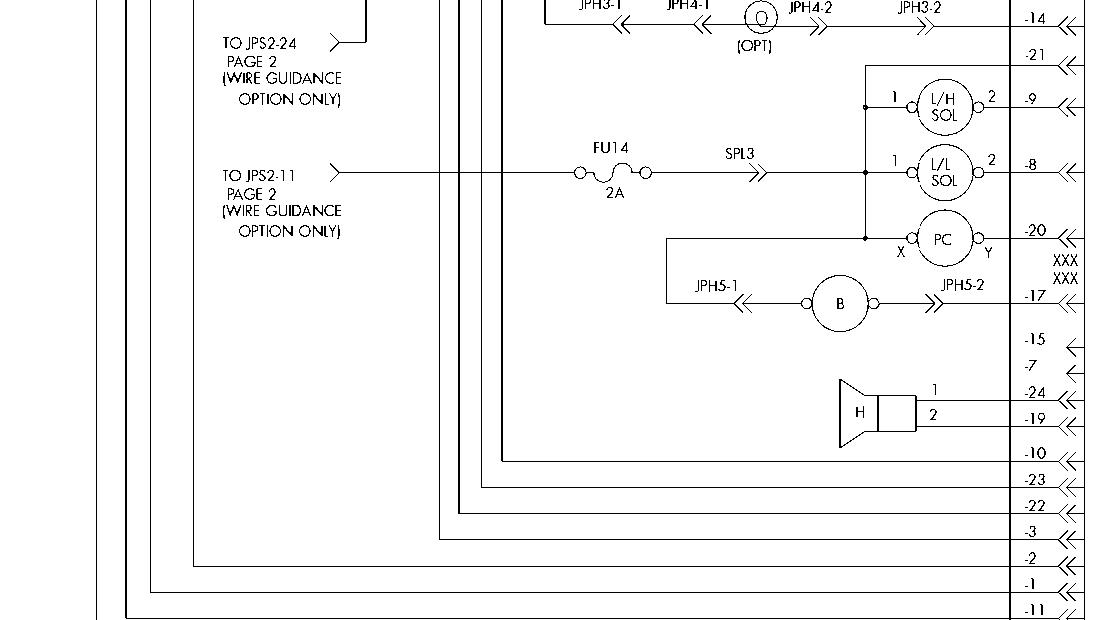
Lift/Lower
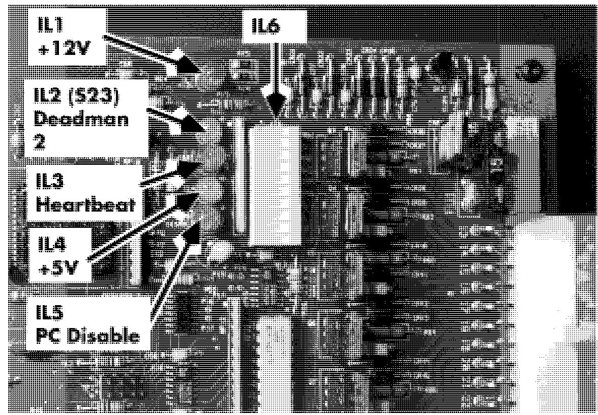
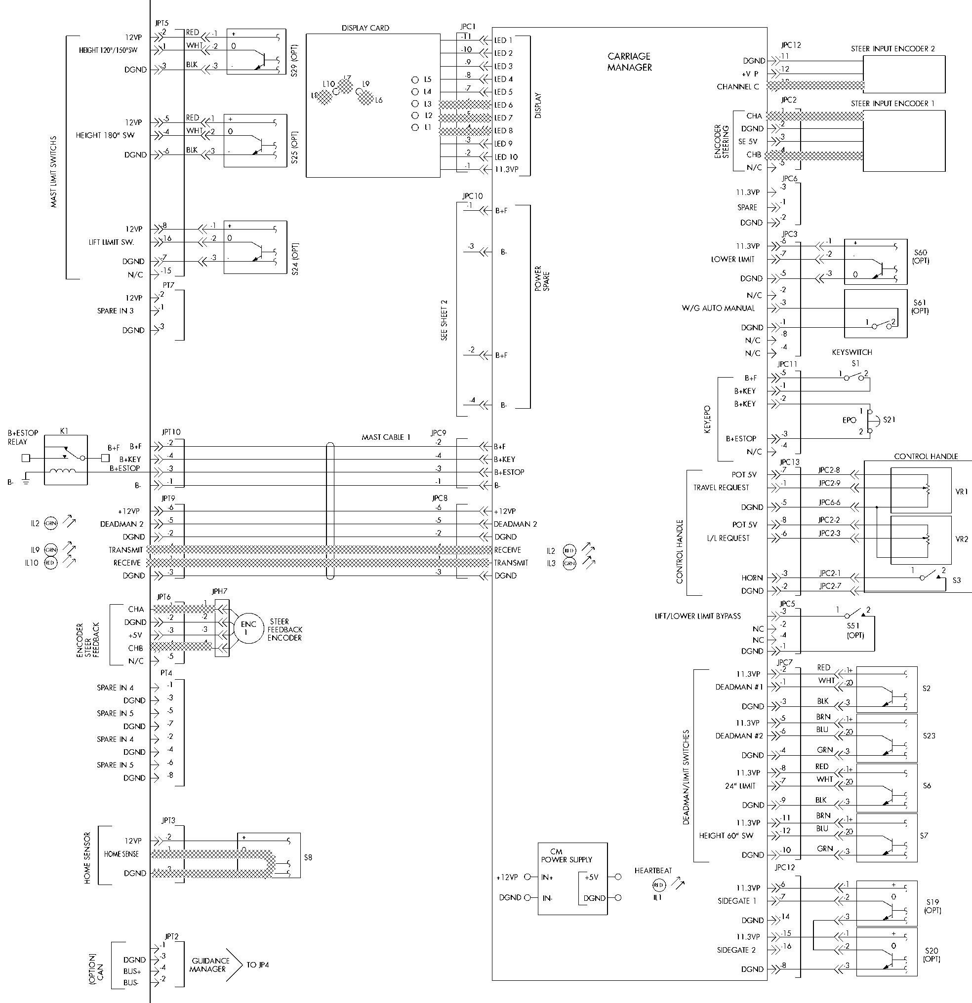
proportional solenoid valve coil at JPT12-8, indicated by the solenoid control LED
(IL6-7)on the steer/tractor manager. The lift/lower proportional valve begins to The lift button commands the carriage to lift. ramp closed (this valve is normally open). When the lift button is pressed, the lift/lower See Figure 9 - 8 on page 9 - 35. proportional solenoid valve (normally open) 6. The lift pump/motor assembly is now stays open while the lift contactor closes. After running and supplying hydraulic pressure the contactor closes and the lift pump motor and flow to the lift cylinders. turns on, the proportional solenoid valve ramps See Figure 9 - 10. closed which forces hydraulic fluid into the cylinders and increases lift speed. The proportional solenoid valve provides a smooth transition between zero speed lift and full speed lift and back to zero speed lift. When the lift button is released, the proportional solenoid opens and the lift contactor opens turning off the lift pump motor. During lift, the load holding solenoid valve remains closed (de-energized)
Lift (55)
The microprocessor on the steer/tractor manager verifies the lift contactor remains closed when commanded closed, and open when commanded open. If either condition is not met, the steer/tractor manager generates a fault code.
See Figure 9 - 9 on page 9 - 36. (The electrical schematic legend is on page 9 - 2.)
1. As the control handle lift switch is closed, a digital ground is applied to JPC13 - 6 on the carriage manager.
2. The carriage manager sends a lift command message to the steer/tractor manager over the transmit/receive lines.
3. The steer/tractor manager provides the negative potential for the lift pump contactor coil (JPT12-18) and the pump contactor coil is energized. The lift pump contactor LED (IL6-5)on the steer/tractor manager indicates the pump contactor coil driver is energized. See Figure 9 - 8 on page 9 - 35.
4. When the lift pump contactor coil is energized, the lift pump contactor tips close supplying B+ to the lift pump motor.
5. The steer/tractor manager provides the negative potential for the lift/lower
00700-CL222-05, 1 5 March 2005