12 minute read
Section 6. Codes and Tests


00700-CL222-05, 1 5 March 2005
Section 6. Codes and Tests
Operator Display Messages
Operator Display
Messages
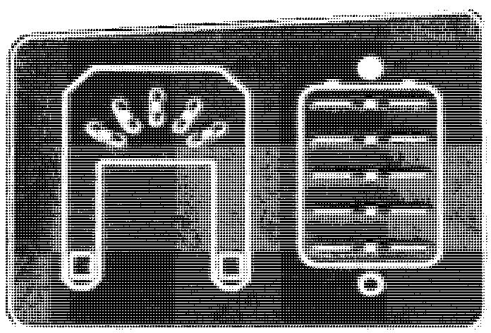
The operator display has two sections, the steering indicator and the battery indicator. See Figure 6-1.
Toyota Orderpicker Model 7BPUE 15 Service Manual
Table Each steering 6-1. indicator message is explained in
Steering lndicator Messages
The steering indicator has five LEDs and shows the current steering direction based on the position of the drive unit. See Figure 6- 1.
Left LED on steady
Truck Condition
II All LEDs scroll in Drive unit position is side-to-side pattern unknown
Display Drive unit in left, end-of-travel zone (more than 65" counter -clockwise)
Mid-Left LED on steady Drive unit in left zone (10-65" counter-clockwise)
II Center LED on steady Drive unit in center zone (within 10" of center)
Mid-Right LED on steady
Right LED on steady
All LEDs blink in unison as the horn beeps
Drive unit in right zone (10-65" clockwise)
Drive unit in right end-of-travel zone (more than 65" clockwise)
In maintenance mode
Messages
Battery Indicator Messages
When the truck is in maintenance mode, the The battery indicator has five LEDs used in steering indication is overridden, and the LEDs three prioritized modes of operation (3 is the flash as the horn "clicks". See "Maintenance highest priority). Mode" on page 6 - 4.
Display
Series of for each digit (all 5 blink together); see " Operator Display Fault Codes" on page 6 - 15
Blinks a single LED to indicate a particular condition; seeTable 6 - 3, "Info Display Messages," on page 6-3.
Single, steady LEDs represent the current I state - of - charge.
The battery indicator will always show the mode with the highest priority that is active. For example, an Info Display message will override a battery state of charge message.
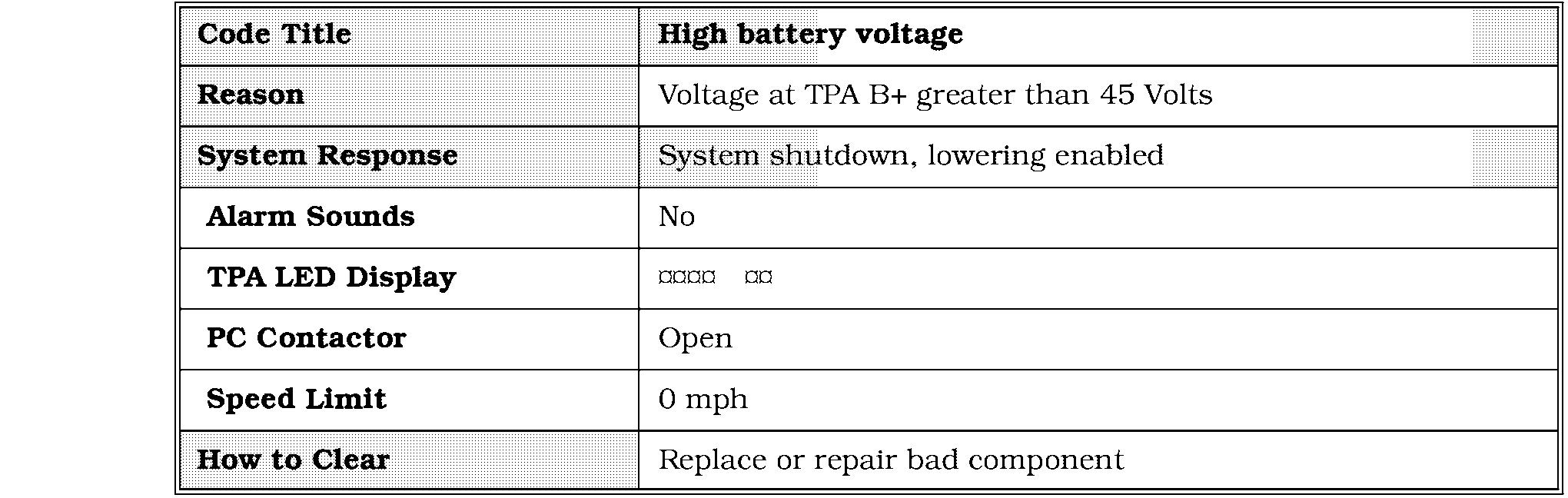
Fault Code
All five LEDs flash in series to identify the fault code. Each series (code) has two digits. If more than one code is present ( " stacked codes"), there are rapid flashes between codes.
Operator Display Messages
displayed. Once these codes are resolved, the next highest codes are displayed until they are resolved.
Each code is explained later in this section. See " Operator Display Fault Codes" on page 6-15.
lnfo Display
Each LED represents a different condition. The table on the following page shows the cause and how to clear each display. There is no limit to the number of stacked codes, but only the highest priority codes will be
Display
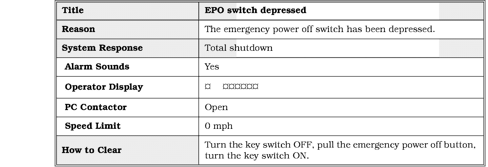
I Top LED blinking EPO depressed
2nd LED from top blinking
(If optional sidegate with interlocks is attached) 3rd LED from top blinking
Cause Deadman pedal must be depressed before 1. Return controls to neutral. you request motion.
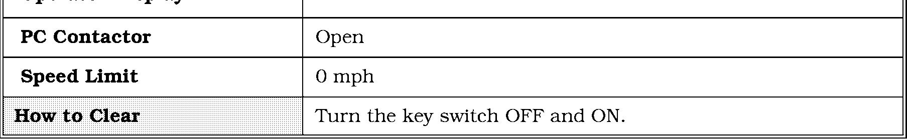
How To Clear
Pull out EPO switch and reset kt switch.
2. Step on deadman pedal.
Steering wheel was not turned (initialized) Turn steering wheel. after key switch turned ON.
Sidegate up when requesting travel or lift/lower.
Lower sidegate.
4th LED from top Carriage reached lift limit (if equipped). Press lift limit bypass switch to blinking continue lifting.
11 Bottom LED blinking I Battery charge is too low. I Use fullv-charged battery. I Table 6-3. lnfo Display Messages
Battery Discharge Indicator (BDI)
On the BDI display, each LED represents a different level. See Figure 6-2.
Maintenance Mode
Maintenance Mode
Maintenance mode allows you to test individual circuits of switches and inputs while the lift truck is stationary or under normal operation.
For example, if you suspect the lift switch is bad, you can verify the switch circuit input to the steer/tractor manager.
Enter the maintenance mode. See " Enter " below. There are two methods for entering Maintenance Mode, using the deadman pedal or using the horn button. After you enter maintenance mode, follow the instructions in "General Testing."
Deadman Pedal Method
1. Turn the key switch ON. The horn beeps three (3)times after self-diagnostics is complete.
2. Within 10 seconds after the three (3)horn beeps, step on and off the deadman pedal 3 - 6 times. The horn will start clicking when the truck is in maintenance mode.
NOTE: The deadman circuit must be transitioned 12 times to enter maintenance mode. If both switches (S2 and S23) are working properly, you only need to step on and off the pedal 3 times. If one is not working, you need to step on and off 6 times.
Horn Button Method
1. Turn the key switch OFF.
2. Hold the horn button and turn the key switch ON. Do not release the horn button.
3. When the BDI display clears, release the horn button.
4. While the BDI display is clear, press and release the horn button once. Each time you press the horn button, one BDI LED lights.
5. Wait for the BDI display to clear. A clear display indicates the first digit was accepted.
NOTE: You must enter the second digit within 3 seconds of entering the first digit.
6. Press and release the horn button once more.
7. Wait a few seconds for the BDI display to clear again. All the BDI LEDs will flash to indicate the password was accepted and the truck is in Maintenance Mode.
General Testing
1. Enter maintenance mode. See " Enter " on page 6 - 4.
2. Request an operation. e.g.-travel, lift, etc. When the switch turns on or off, or an analog input crosses a threshold, the truck determines whether the circuit is good or bad.
If the circuit is good, the horn clicks and the heartbeat LEDs on the steer/tractor manager and carriage manager, and the steer indicator LEDs on the operator display blink during the operator request. If the circuit is bad, the horn does not click and the LEDs do not blink during the operator request.
The following standard switches can be tested in maintenance mode:
Steer Home Switch (S8)
Deadman (S2 and S23)
Horn (S3)
24 " Limit (S6);see Note below 60 " Height (S7);see Note below 120/ 150 " Height (S29); see Note below Emergency power off (S21)
NOTE: To test S6, S7, S24, S25, S29 and S60, step on deadman pedal and lift the operator platform. Each switch is tested as it passes its activation rail.
The following optional switches can also be tested in maintenance mode:
Maintenance Mode
NOTE: This test will not work if you step on the Page deadman pedal.
Lower limit (S60);see Note on previous
Auto manual (S61)
2. Rotate the steering wheel.
3. See Table 6 - 4 below for test results. This 180" Height (S25); see Note on previous velocity-sensitive feedback tells you if the Page. system is receiving steering requests from the steer encoder.
Lift limit (S24)
Throttle Potentiometer Test
1. Entcr maintenance mode. See "Enter" on page 6-4. The horn should click and the 2nd BDI LED should blink 3 - 4 times for each direction.
Horn and LED Response
2. Rotate the throttle (via the control handle) from neutral to maximum speed in each direction.
If the horn does not click and the LED does not blink, the analog voltage is outside the acceptable range. Test the resistance of the throttle potentiometer.
Learning Throttle & Lift Potentiometer
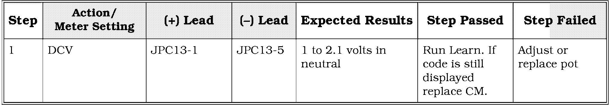
There are two methods for learning the neutral position of the throttle potentiometer. You can use the procedure in the following table or use the MashWare program. See "Flashware Program" on page 10 - 2.
Technician Action
Key ON, EPO in, Deadman pedal down Key OFF
Key ON, wait for 3 horn chirps EPO out, EPO in EPO out, EPO in EPO out, horn chirps 10 times when truck has learned neutral position of throttle potentiometer
Deadman pedal up
Key OFF, Key ON
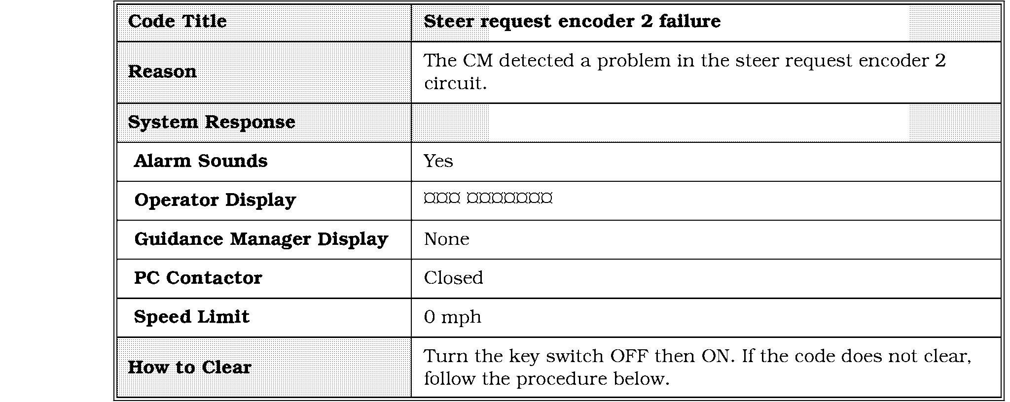
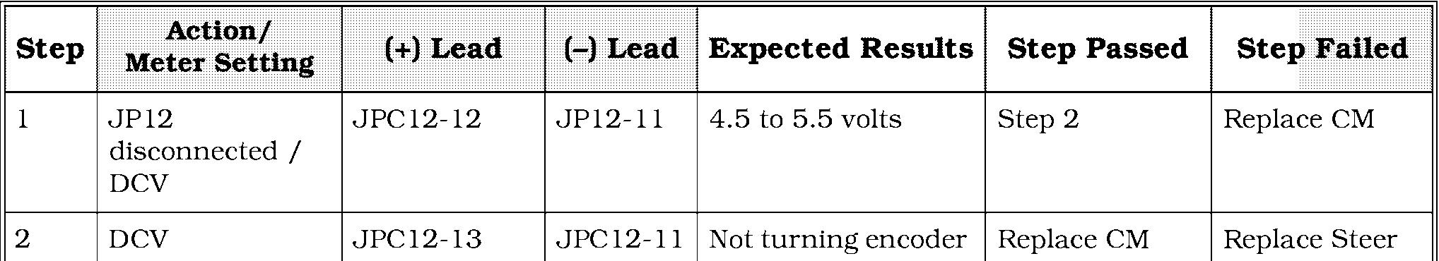
Steer Encoder Test
1. Enter maintenance mode and step OFF the deadman pedal. See " Enter " on page 6 - 4.
Horn clicks and LEDs blink at the same rate you rotate the steering wheel. Horn clicks and LEDs blink at a different rate than you rotate the steering wheel. Horn and LEDs do not respond when you rotate the steering wheel. Table 6-4. Steer
Diagnosis
Steer encoder is good. Steer encoder is missing one channel. Steer encoder or cable is bad.
Corrective Action
None required. Do not continue through the steer encoder test. Test the individual channels. Go to step 4. Replace the steer encoder.
Encoder Test Results
4. Measure the voltage at PC 2 -1 (Channel A) and PC 2 - 4 (Channel B) with respect to PC 2 - 2 (DGND) as you rotate the steering wheel.
5. The voltage should vary as the steering wheel is rotated.
6. If the voltages do not match the table above, replace the steer encoder.
Section 6. Codes and Tests
Traction Power Amplifier
Fault Codes
Traction Power Am ifie
Toyota Orderpicker Model 7BPUE 15 Service Manual
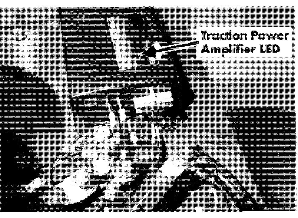
An internal microcontroller automatically checks the function of the traction power
Fault Codes amplifier. When this microcontroller detects a fault, it signals the appropriate fault codethrough the light emitting diode (LED) on the front of the traction amplifier. These are not the codes that appear on the operator display and tractor manager.
Under normal operation, the LED flashes a single flash at approximately one flash per second (a " heartbeat " indicator). A two-digit flash code signals the power amplifier has detected a fault within itself. The code continues flashing until corrected.
TPA Code LED Off
TPA Code LED Solid On
Corrective Actions and Checks
TPA Code Heartbeat
Corrective Actions and Checks

None. System functioning properly. 00700-CL222-05, 1 5
TPA Code 1,1

TPA Code 1,l
Corrective Actions and Checks
TPA Code 1,2
Corrective Actions and Checks
TPA Code 1,3
TPA Code 1,3


Corrective Actions and Checks
TPA Code 2,l
TPA Code 3,3
TPA Code 3,3
Corrective Actions and Checks
Action/ Meter Setting S 1 and S2 wires disconnected from TPA/OHMs
Step 1 S1 wire
2 S 1 terminal on TPA S 1 and S2 wires disconnected from TPA/OHMs
(+) Lead S2 terminal on TPA
(-) Lead
S2 wire
Expected Results
About 1 OHM
Turn key ON = 0 volts
Step on deadman pedal = 12 to 13 volts for about one second
Step Passed 00700
Step Failed
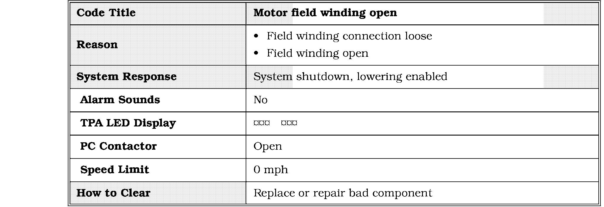
Step 2 Troubleshoot wires to motor and motor field
Step 1 Replace TPA
TPA Code 4,1
TPA Code 4,l
NOTE: After one minute of inactivity, the PC contactor will drop out. This will activate a blinking 4,l code. This is normal operation and should not be considered a fault.
Corrective Actions and Checks

TPA Code 4,3
Corrective Actions and Checks
TPA Code 4,3

Corrective Actions and Checks been parked in a freezer for an hours, take it amount of time out of the freezer
Step
TPA Code 4,3 Park the truck and allow it to cool down for a few hours
Code clears Inspect the mounting of the TPA to the truck frame. It must be tight against the from to dissipate heat properly. If tight, investigate the duty cycle use of the truck.
Replace the TPA
Code 1,3
Code 1,3
Corrective Actions and Checks
NOTE: Use step 1 if the contactor tips do open when the lift request is removed. Use steps 2 and 3 if the contact tips do not open when the request is removed.


Code 1,4
Code 1,4
Corrective Actions and Checks

NOTE: Use steps 1 and 2 if the contactor tips do close when a lift is requested. Use steps 3 and 4 it the contact tips do not close when a lift is requested.

1. Mast switches (S6. S7. S25. S29) wcrc dctcctctl out ol' sccl~~cnccwhich indicates there is a problem with a switch or rail.
2. Sol'twwrc is not conligurctl correctly or is conligurctl for the wrong tr~rck.(Looking for a switch not on the tnlck.)

Corrective Actions and Checks
NOTE: Not opening the 24 in. switch with lift request and motor running more than 10 seconds, will cause this code.
Check all mast switches per Figure 5 - 2 on page 5 - 10 and the steps in the chart below.
connects to.

Corrective Actions and Checks


Corrective Actions and Checks

Corrective Actions and Checks
Corrective Actions and Checks
00700-CL222-05, 1 5 March 2005

Corrective Actions and Checks

1. If the code does not clear, follow the

Code 2,6
Code 2,6
Corrective Actions and Checks
Full lower = less than 2.8 volts

Full lift = more than


Section 6. Codes and Tests Toyota Orderpicker Model 7BPUE 15 Service Manual
Code 3,2
Code 3,2
Corrective Actions and Checks
NOTE: If the drive unit will steer left and right, start with step 1. If the drive unit will not turn in one or both directions, start with step 4.

At rest = 0 volts Turning tiller fast left = 4.7 volts

Code 3,3
Code 3,3 Operator Display
Corrective Actions and Checks
NOTE: Steering with the drive tire off the floor will cause this code.
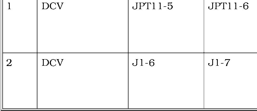
Breakout cable JPT8-1 connected between STM and Steer Power Head/DCV
Breakout cable JPT8-10 connected between STM and Steer Power Head/DCV
Breakout cable JPT8-6 connected between STM and Steer Power Head/DCV
Breakout cable JPT8-15 connected between STM and Steer Power Head/DCV
At rest = 4.81 volts
Turning tiller fast Right =O volts
At rest = 4.81 volts
Turning tiller fast Left =O volts
At rest = 0 volts
Turning tiller fast Left = 4.7 volts
At rest = 0 volts
Turning tiller fast Right = 4.7 volts
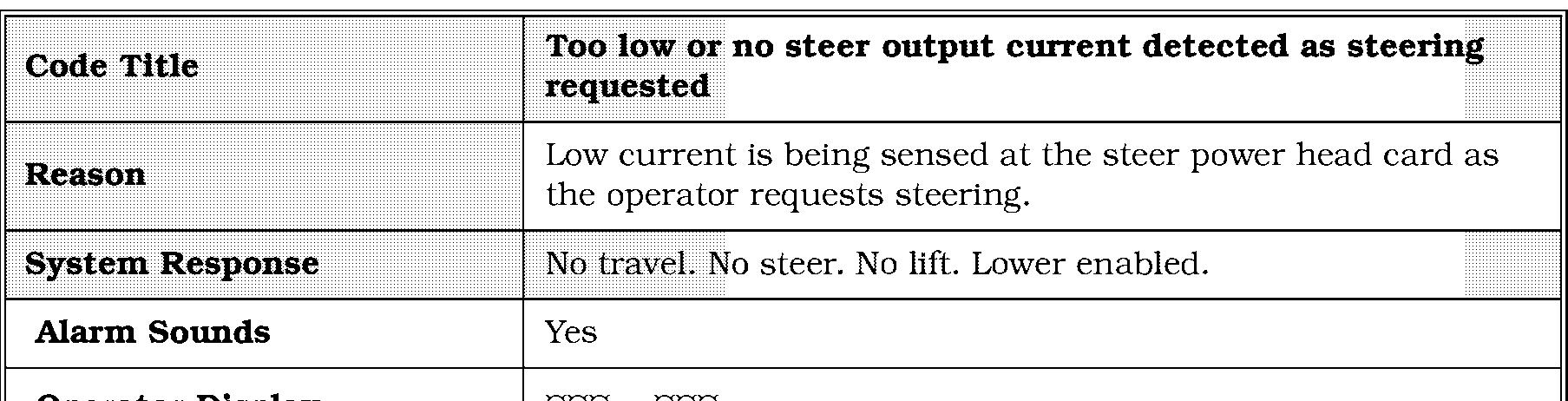

Code 3,4 head senses current in the steer motor circuit.
Corrective Actions and Checks
Corrective Actions and Checks
1 Breakout Cable JPT8-5 connected between STM and Steer Power Head / DCV

Approx. 4.85 volts Steering or not. If low, 0 volts truck thinks it is current limit and step failed

Replace STM
1. Remove steer motor and gear box and make sure it will turn with power.
2. With steer motor removed make sure drive unit turns freely.
3. Replace Steer power head.

00700-CL222-05,

Corrective Actions and Checks
NOTE: Disconnect S2 and step on the deadman pedal. If the code still appears troubleshoot the S2 circuit starting with step 1. If the truck does not recognize the deadman pedal being depressed troubleshoot S23 starting with step 6.


Code 4,2
Code 4,2
Corrective Actions and Checks
Step
Action/ Meter Setting
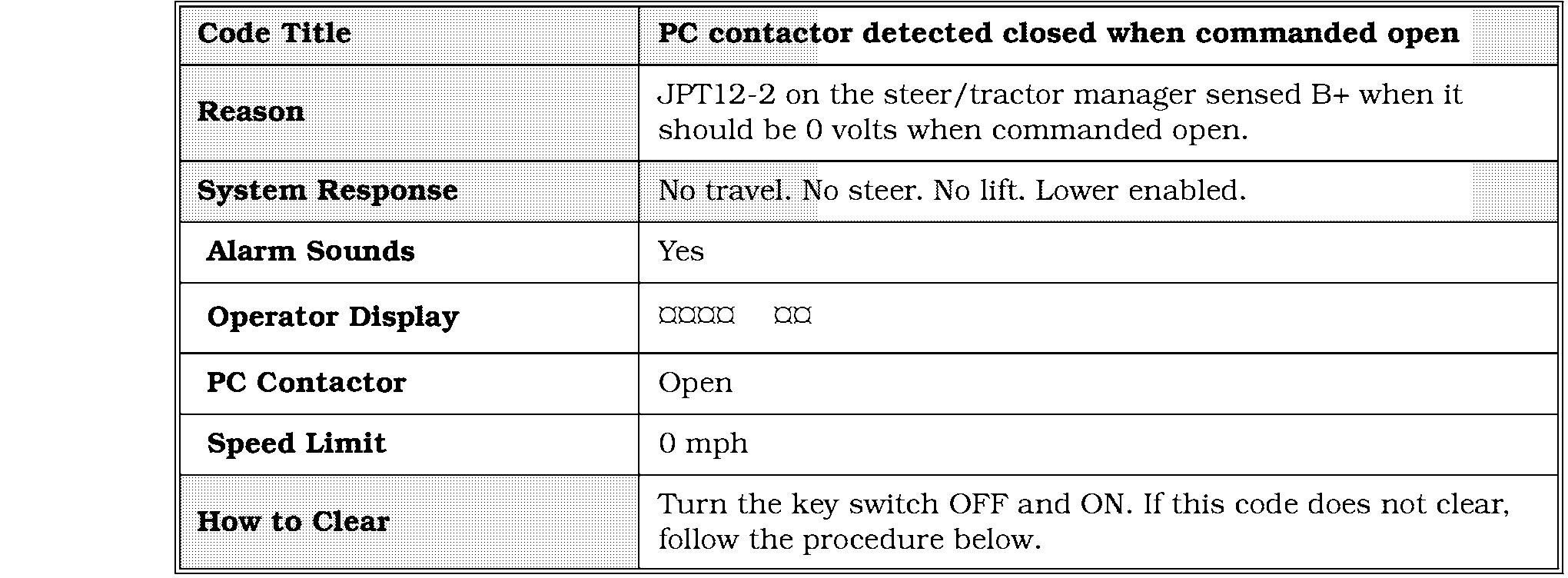
If contactor tips N/A are closed with Key OFF
Key on PC JPT12-20 closed, wait for 30 seconds and see if contactor opens/DCV
Key on PC JPT12-2 closed/DCV
Check contactor for burnt tips and mechanical binding
0 volts when contactor should be closed. B+ when contactor should be open
0 volts when contactor should be closed. B+ when contactor should be open
Step Passed Step Failed
Step 2
Step 3
Repair or replace the contactor
Replace STM
If OK and code still appears replace STM
Troubleshoot wire at JPT12-2 for shorts to B+
Code 4,3 after the PC contactor was commanded closed.
Corrective Actions and Checks

Expected
Step
Step 3
Code 4,3
Step 4
Step Failed
Replace fuse Inspect PC contact tips. Troubleshoot wire at JPT12-2 for an open.
Step 1
Troubleshoot circuit from JPT12 - 21 B+ ESTOP relay Replace STM
Corrective Actions and Checks
1. If a communication failure occurs, the steer/tractor manager microprocessor will continue to attempt communication. This communication will be evident by viewing the RECEIVE (IL3/IL10) and TRANSMIT (IL9/IL4)LEDs on the carriage manager and the steer/tractor manager. The carriage manager will then send (initiate)a message to the steer/tractor manager and it will acknowledge the message by flashing its TRANSMIT LED. It is possible to determine the faulty module (carriage manager or steer/tractor manager) by viewing the LEDs. See Figure 7 - 5 on page 7 - 8 and Figure 7 - 8 on page 7-9.
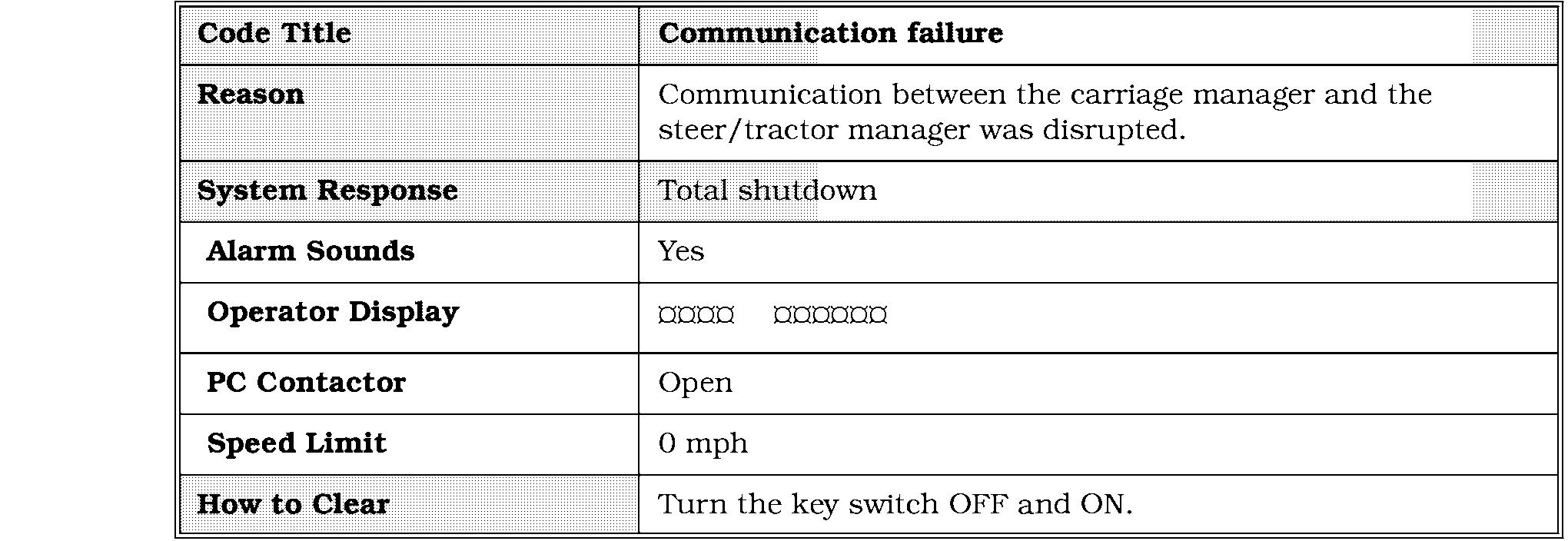
2. If the failure is on the carriage manager, the RECEIVE LED (IL3) will be flashing but the TRANSMIT LED (IL4)will not. Check over-the-mast cable. If cable is OK, replace carriage manager.
3. If the failure is on the steer/tractor manager, the RECEIVE LED (IL10)will be flashing but the TRANSMIT LED (IL9)will not. Check over-the-mast cable. If cable is OK, replace steer/tractor manager.
Code 4,8
Corrective Actions and Checks


Corrective Actions and Checks


Step 2
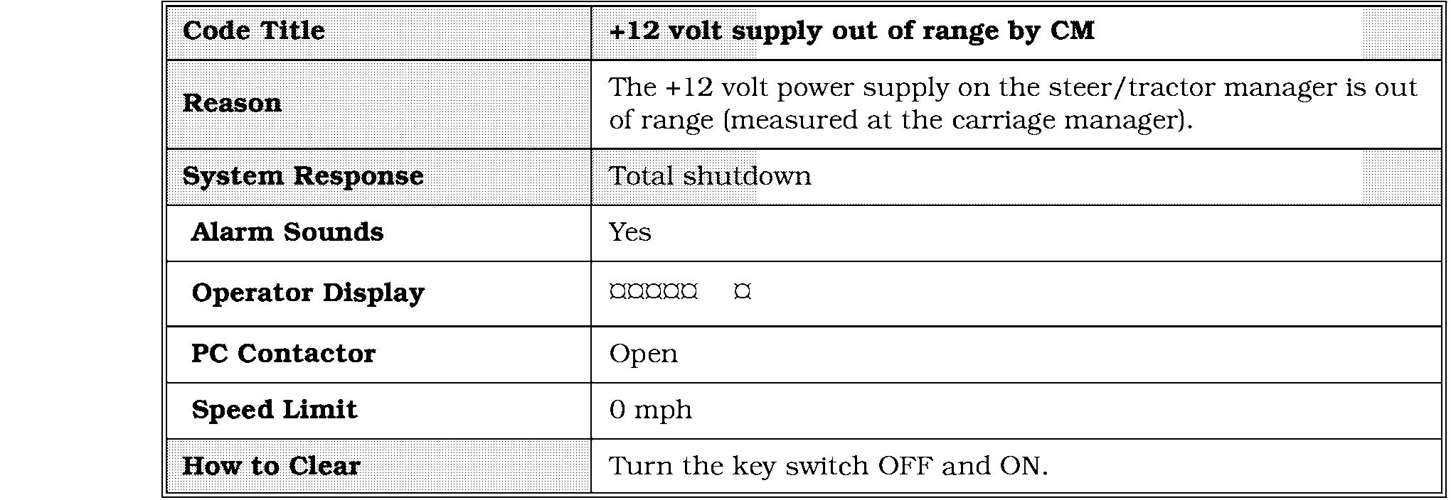
Troubleshoot the wiring and device that pulls down the 12 volts.
Connect devices to the CM one at a time.
Troubleshoot the wiring and device that pulls down the 12 volts.
Test overmast cable for shorts. If OK replace CM
Code 5,2
Code 5,2
Corrective Actions and Checks
NOTE: If this code is intermittent check truck for shorts to frame and verify static straps are clean and contacting the floor.


Code 5,s
Corrective Actions and Checks
NOTE: If this code is intermittent check truck for shorts to frame and verify static straps are clean and contacting the floor.

6,l
Corrective Actions and Checks
1. If the code does not clear, follow the
If Code 6,l is gone troubleshoot wires and speed encoder. Is code is still present proceed to step 7 Step 5

Check FU14 if OK
Troubleshoot wiring to STM
Troubleshoot wiring to TP4
Step 4
Replace Steer Controller 00700-CL222-05,


Code 6,2
Code 6,2
1. If the code does not clear, follow the
Corrective Actions and Checks
the code shown on the Steer Controller card
NOTE: Check adjustment of the line driver. Check for mechanical binding in the Drive Unit and steering gear box. Run Learn for Guidance. Check setting for Heading Angle and Distance from Wire in configure. If intermittent check for shorts to frame.

Code 6,3
Code 6,3
Corrective Actions and Checks
NOTE: Check adjustment of the line driver. Check for mechanical binding in the Drive Unit and steering gear box. Run Learn for Guidance. Check setting for Heading Angle and Distance from Wire in configure. If intermittent check for shorts to frame.


