1 minute read
Section 9. Theory of Operation


Tracins Lesend - Electrical = B+ Circuit = B- Circuit= Signal VHMBMHHL = 12V/5V


Lower (54)
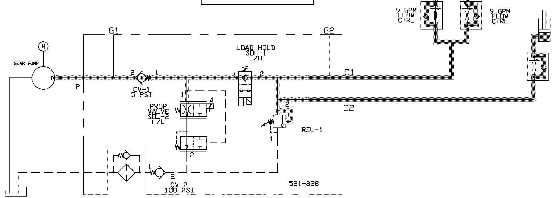
The lower button commands the carriage to lower. When the lower button is pressed, the lift/lower proportional solenoid valve closes and the load holding solenoid valve opens. The proportional valve opens and allows hydraulic fluid to return from the lift cylinders to the reservoir.
When lower is no longer requested, the proportional valve opens and the load holding valve closes.
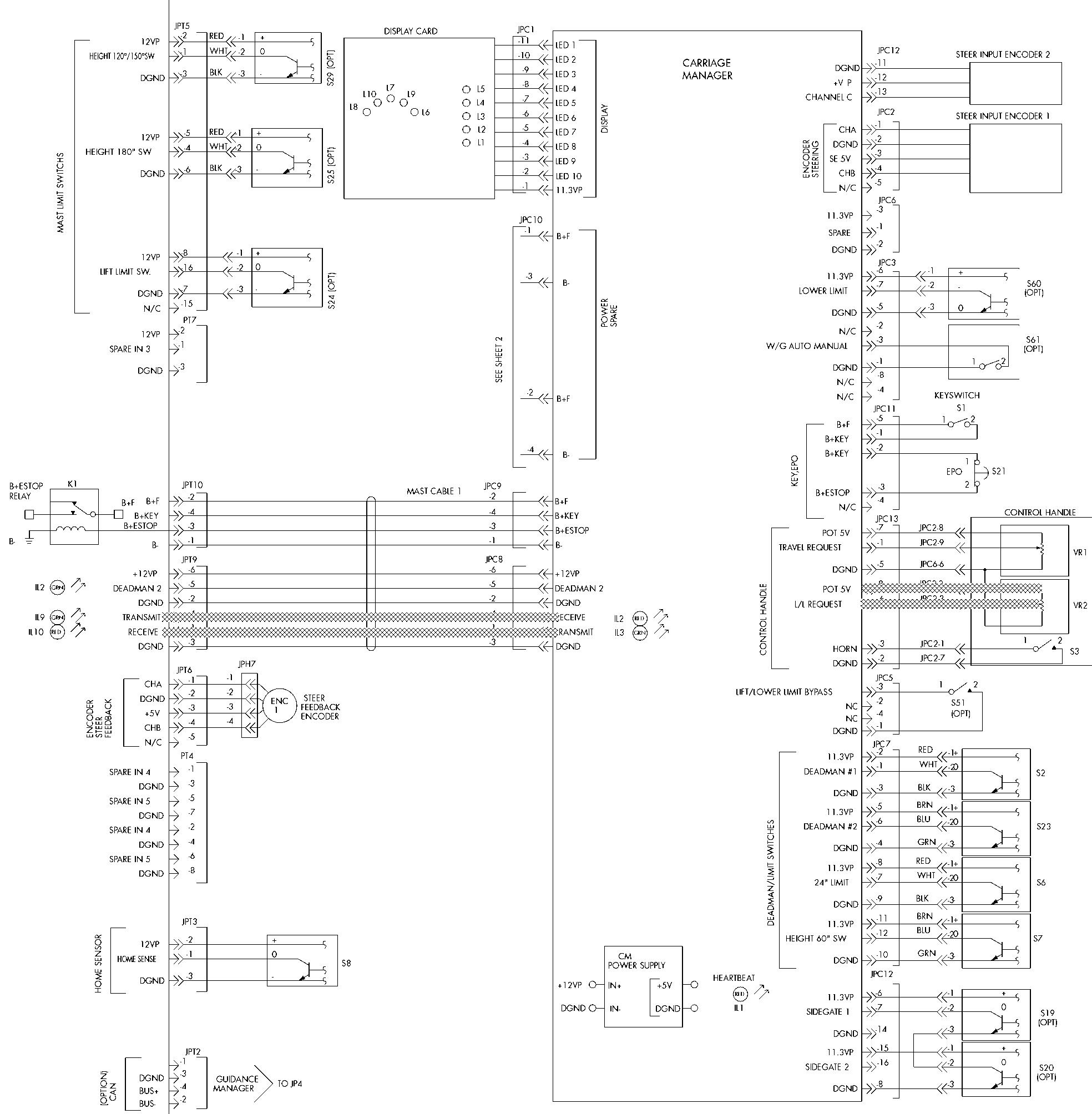
See Figure 9 - 13 on page 9-44. (The electrical schematic legend is on page 9-2.)

1. As the control handle lower switch is closed, a digital ground is applied to JPC13-7 on the carriage manager.
2. The carriage manager sends a lower command message to the steer/tractor manager over the transmit/receive lines.
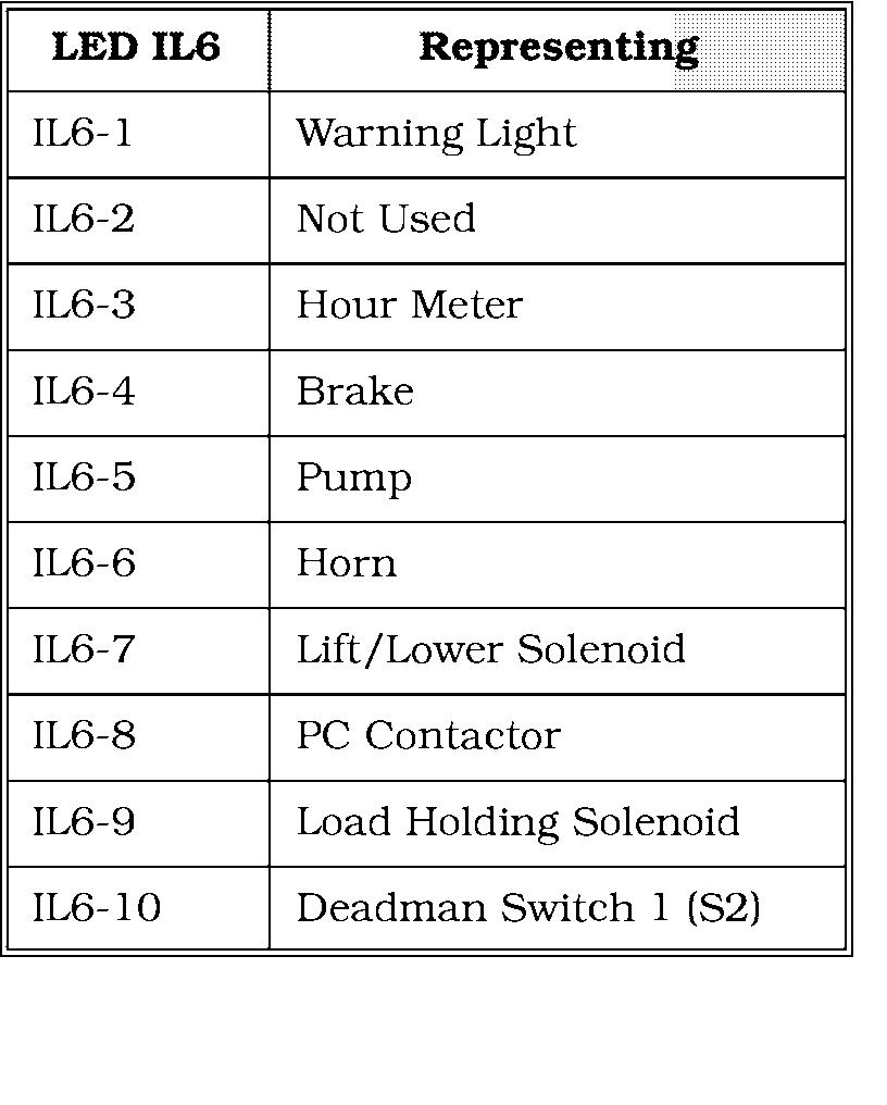
3. The steer/tractor manager provides the negative potential for the lift/lower proportional valve coil at JPT12-8, indicated by the load holding solenoid LED (IL6-7)on the steer/tractor manager. See Figure 9- 11 on page 9-4 1. The lift/lower proportional valve ramps closed (this valve is normally open).
4. The steer/tractor manager provides the negative potential for the load holding valve coil at JPT12-9, indicated by the load holding solenoid LED (IL6-9).See Figure 9- 11 on page 9-4 1. The coil energizes and the load holding valve opens.
5. The steer/tractor manager varies the negative potential for the lift/lower proportional valve coil at JPT12-8, indicated by the load holding solenoid LED. The lift/lower proportional valve gradually opens allowing hydraulic fluid to return to the reservoir. See Figure 9-12.