1 minute read
Section 9. Theory of Operation Toyota Orderpicker Model 7BPUE 15 Service Manual


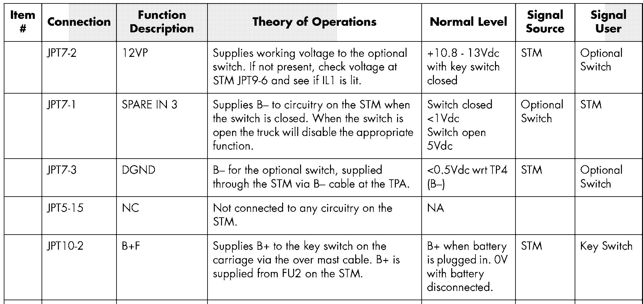
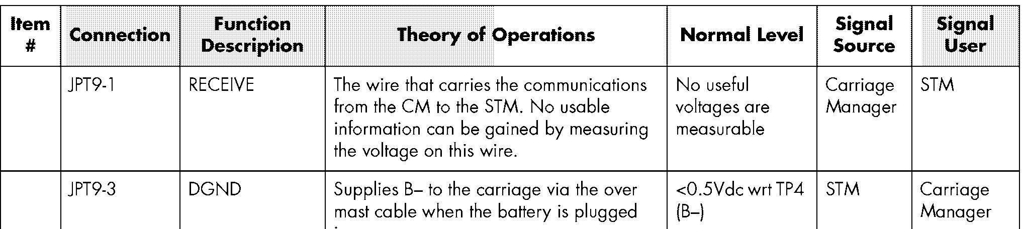
Pinout Matrix
Supplies B+ Key to the circuitry on the STM via the over mast cable when the key switch is
Supplies B+ ESTOP to the K1 relay coil on the STM via the over mast cable when the EPO switch (S21) is closed. This closes the relay and supplies B+ ESTOP Relay to circuits on the STM.
Supplies B- to the carriage via the over mast cable when the battery is plugged In.
Supplies 12V from the STM power supply to the Carriage Manager via the over mast cable. The 12V is used to power the CM power supply and supplies voltage to all components using the 1 1.3VP. If not present, check voltage at STM JPT9-6and see if IL1 is lit.
Output from deadman switch S23 informs the microprocessor on the STM that the switch is closed and lights 112 on the STM.
Supplies B- to the carriage via the over mast cable when the battery is plugged In.
The wire that carries the communications from the STM to the CM. No usable information can be gained by measuring the voltage on this wire.
B+ with key switch closed.
OV with key switch open.
B+ with the EPO switch closed.
OV with the EPO Open <O.SVdc wrt
+10.8 - 13Vdc with key switch
This is a square wave generated whenever there is movement of the Steer Feedback Encoder. Voltage varies between about 4Vdc and about OVdc as the encoder shaft rotates. The frequency varies directly with the speed of the Drive Motor. The STM uses the quadrature phase relationship between CH A & B to determine direction and speed.
B- to the steer feedback encoder.
Positive supply from the STM power supply to the steer feedback encoder.
This is a square wave generated whenever there is movement of the Steer Feedback Encoder. Voltage varies between approx 4Vdc and OVdc as the encoder shaft rotates. The frequency varies directly with the speed of the Drive Motor. The STM uses the quadrature phase relationship between CH A & B to determine direction and speed.
Not connected to any circuitry on the STM.
Input from optional switch connection.
B- for optional switch
Input from optional switch connection
B- for optional switch
Input from optional switch connection should vary between >3Vdc to < 1 Vdc as encoder shaft is rotated slowly. to 5.5V should vary between >3Vdc to < 1Vdc as encoder shaft is rotated slowly.


