
2 minute read
Section 7. Component Procedures


Forks
Forks
Remove
1. Raise operator platform high enough to reach bottom of forks.
2. Block operator platform with 4 x 4" (10 x 10 cm) upright block.
3. Secure fork to hoist using a suitable strap or chain.
4. Remove one socket head cap screw from underneath fork at tractor end. See Figure 7- 142.

5. Remove snap ring from pivot pin in mounting block of fork.
Install
1. Hold new fork in place underneath operator platform.
2. Install pivot pin through fork.
NOTE: Always use new snap rings when assembling components.
3. Install new snap ring in pivot pin. See Figure 7- 143.
4. Install correct amount of washers or shim at back side of fork to maintain a level fork. See Figure 7 -144.
5. Install socket head cap screw at tractor end of fork.
6. Remove block from operator platform.
7. Lower operator platform to floor and make sure forks are level. If forks are not level, add more shim to fork.
The fork will drop in step 6. It weighs approximately 150 Ib. (68 kg).
6. Drive out pivot pin. The fork, washers or shim will drop. See Figure 7 -143.
7. Replace damaged fork.
Mast Section
Pallet Clamp
Install
1. Install the pallet clamp assembly on the platform front plate. Secure it with four (4) M10 X 20 screws. Torque to 30 ft. lbs. (41 Nm)
2. Install the pedal assembly to the platform main support plate. Secure it with two (2) M8 X 20 screws. Torque to 15 ft. lbs. (20 Nm).
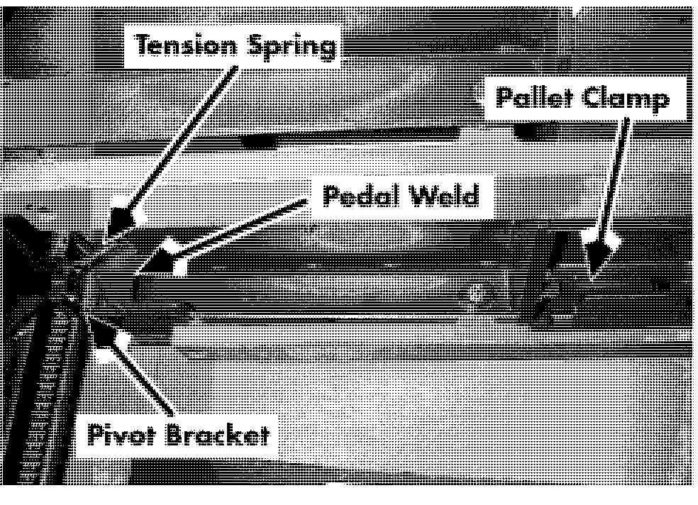
3. Hook the tension spring into the 1/4-inch holes in the pivot bracket and pedal weld in the pedal assembly. See Figure 7-145.
4. To extend the spring so you can connect the cable assembly, slide a 2-inch-wide block between the left hand pallet support and the pallet clamp on the pallet clamp assembly.
5. Install the cable bracket on the pedal assembly. Secure it with the M8 X 10 shoulder bolt and M8 hex nut. Torque to 15 ft. lbs. (20 Nm).
6. Place the cable assembly in the cable bracket and secure with the M6 hex nuts. Finger-tighten the hex nut closest to the pedal mounting and leave the other nut loose.
7. Remove the 2-inch block you used in Step 4.
8. Adjust the hex nut closest to the pedal mounting until there is a 90' angle
Section 7. Component Procedures
Pallet Clamp between the pallet clamp and the left hand pallet support. Torque the remaining hex nut to 2 1 ft. lbs. (29 Nm).
Load Wheels
Load Wheels
Use extreme care whenever the truck is jacked up. Keep hands and feet clear of from the vehicle while jacking the truck. After the truck is jacked, place solid blocks beneath it to support it. DO NOT rely on the jack alone to support the truck. See "Jacking Safety" on page 2-1 1.
1. Raise operator platform approximately 1 ft. from the floor. Place a 4 x 4 inch (10 x 10 cm) block across top of baselegs underneath platform.
2. Turn key switch OFF and disconnect battery.
3. Jack up baseleg high enough to clear load wheel from under baseleg. Block under baseleg.
4. Remove snap ring from axle. See Figure 7- 146.

5. Drive out axle. The load wheel will fall out of baseleg. See Figure 7- 146.
6. Replace load wheel assembly.
7. Drive axle back through wheel and baseleg.
8. Install snap ring.
9. Remove blocks.
Mast Section Skid Pads
Skid Pads
Location
There are two skid pads on each truck.
Inspection
1. Check clearance between each skid pad and floor.
2. If clearance is more than 3/4 inch (19.1 mm) on either side, replace skid pad. See procedure below.
Use extreme care whenever the truck is jacked up. Keep hands and feet clear of from the vehicle while jacking the truck. After the truck is jacked, place solid blocks beneath it to support it. DO NOT rely on the jack alone to support the truck. See "Jacking Safety" on page 2-1 1.
Replacement
Weld new skid pad inside worn skid pad. Clearance from floor should be 3/4 inch (19.1 mm).


