Section 9. Theory of Operation
Toyota Orderpicker Model 7BPUE 15 Service Manual
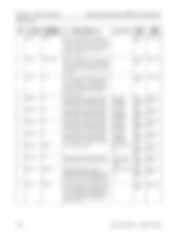
Pinout Matrix
her side you should see around
1.5 in. to the right you should see around 15mVAC. 1.5 in. left you should see around 75mVAC. JPW2-5
TO
Communication lines used by the steer controller card to tell the antenna card which frequency it should be looking for.
No useful voltages are measurable
Steer Controller Card
Antenna Card
JPW2-6
T1
Communication lines used by the steer controller card to tell the antenna card which frequency it should be looking for.
N o useful voltages are measurable
Steer Controller Card
Antenna Card
JPW2-7
T2
Communication lines used by the steer controller card to tell the antenna card which frequency it should be looking for.
N o useful voltages are measurable
Steer Controller Card
Antenna Card
JPW2-8
T3
Communication lines used by the steer controller card to tell the antenna card which frequency it should be looking for.
N o useful voltages are measurable
Steer Controller Card
Antenna Card
JPW2-14
AGRD
B- to the antenna card.
<O.SVdc wrt TP4
(B-1
Steer Controller Card
Antenna Card
+10.8 - 13Vdc with key switch closed
Steer Controller Card
Antenna Card
<O.SVdc wrt TP4
Steer Controller Card
Antenna Card
Antenna Card
Filter Card
JPW2-15
12 V
Positive supply from the steer controller card power supply for the antenna card.
JPW2-13
SHIELD
Shield that helps reduces noise interference in the AC voltage from the antenna card. It must be connected to Bon the at the filter card connection only.
JPW1-1
RIGHT
This is the input from the left tractor sensor coil to the filter card. Centered over the wire you should see around 32mVAC. 1.5 in. to the right you should see around 15mVAC. 1.5 in. left you should see around 75mVAC.
(B-)
00700-CL222-05, 1 5 March 2005


