Section 9. Theory of Operation
Toyota Orderpicker Model 7BPUE 15 Service Manual
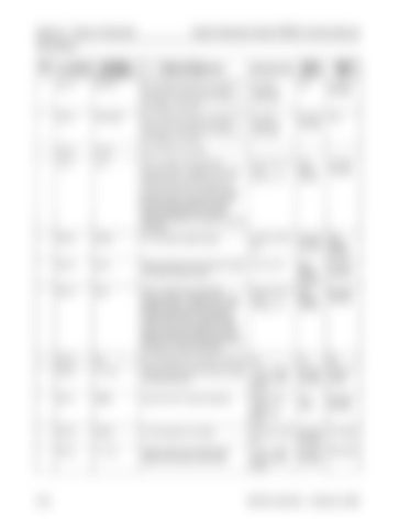
Pinout Matrix
the steer wheel is spun by the operator. The C M uses the quadrature phase relationship between CH A & B to determine direction and speed of steering requested. JPC2-2
DGND
B- to the steer request encoder.
<.5Vdc wrt TP4 (B-)
Carriage Manager
Steer Request Encoder
JPC2-3
SE 5V
Positive supply from the C M power supply to the steer request encoder.
4.5V to 5.5V
Steer Request Encoder
Carriage Manager
JPC2-4
CHB
This is a square wave generated whenever there is movement of the Steer Request Encoder. Voltage varies as the encoder shaft rotates. The frequency varies directly with the speed the steer wheel is spun by the operator. The C M uses the quadrature phase relationship between CH A & B to determine direction and speed of steering requested.
Not turning= 5V or OV. Turning= 2.2V
Steer Request Encoder
Carriage Manager
JPC2-5
NC
Not connected to any circuitry on the CM.
NA
NA
NA
JPC6-3
11.3 VP
Positive supply from the C M power supply for optional devices.
+10.8 - 13Vdc with key switch closed
Carriage Manager
Optional Device
JPC6-1
SPARE
Input from the S10 switch (optional).
Switch closed <lVdc Switch open 5Vdc
S10 Switch
Carriage Manager
JPC6-2
DGND
B- to the optional S10 switch.
<0.5Vdc wrt TP4
Carriage Manager
S10 Switch
Carriage Manager
S60 Switch
(B-1 JPC3-6
1 1.3 VP
Positive supply from the STM power supply for the optional S60 switch.
+10.8 - 13Vdc with key switch closed
00700-CL222-05, 1 5 March 2005


