Section 9. Theory of Operation
Toyota Orderpicker Model 7BPUE 15 Service Manual
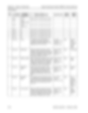
Pinout Matrix
CURRENT LIMIT
JPT8-12
NC
Same as PSI on the steer power head.
JPT8-13
NC
Same as PSI on the steer power head.
JPT8-14
NC
Same as PSI on the steer power head.
JPT12-13
B+PCF
B+ supplied to the warning light, P contactor coil and the Travel Alarm. It comes from the STM through FU1 and is dependant on B+PC at JPT12-1.
B+ w/PC contactor closed OV w/PC contactor open
STM
Warning Light, P contactor coil and Travel Alarm
JPT12-18
PUMP CTRL
Path for the STM to supply B- to the P contactor. There is also an LED (116-5)on the STM that will light when B- is supplied to the coil. Voltages are measured with meter leads on the coil X and Y.
Not activated= 20.5V. Activated= less than 1 V.
STM
P Contactor
JPT12-16
TRAVEL ALARM
Path for the STM to supply B- to the Travel Alarm. There is also an LED (116-2)on the STM that will light when B- is supplied. Voltages are measured with meter leads on terminals 1 and 2 of travel alarm.
Not activated= 20.5V. Activated= less than 1 V/
STM
Travel Alarm
JPT12-14
WARNING LIGHT
Path for the STM to supply B- to the Not activated= warning light. There is also an LED (116-1) 20.5V. on the STM that will light when B- is Activated= less supplied. Voltages are measured with than 1 V. meter leads on terminals 1 and 2 of the light.
STM
Warning Light
JPT12-21
B+ ESTOP RELAY
B+ supplied to the load holding and lift lower solenoids, PC contactor coil and the brake coil. It comes from the STM through the K1 relay and is dependant on B+F from FU2.
B+ w/EPO closed OV w/EPO open
STM
LH, LL solenoids, PC and Brake coils, Steer Controller Card
JPT12-9
L/H SOL CTRL
Path for the STM to supply B- to the L/H solenoid. There is also an LED (116-9)on the STM that will light when B- is supplied to the coil. Voltages are measured with meter leads on solenoid coil 1 and 2.
Not activated= 20.5V. Activated= less than 1 V.
STM
Load Holding Solenoid Coil
00700-CL222-05, 1 5 March 2005


