Section 8. Wire Guidance
Toyota Orderpicker Model 7BPUE15 Service Manual
Install Kit Components a. 3 lockwashers (P/N 00590-02851-71) b. 3 washers .(P/N 00590-03092-7 1)
Feed the harness through the notch in the housing. See Figure 8- 11.
,
c. 3 screws (P/N 00590-46033-71)
8. Install the snap ring (P/N 00590-46047-71) on top of the bearing in the housing. See Figure 8- 11. 9. Use gasket flange sealant (Loctite Ultra Black 598) and fill the notch in the housing. See Figure 8- 11. 10. Connect PH6 of cable assembly (P/N 00590-45863-71) to the encoder harness connector JH6, then route the harness wires along the drive motor cables. Use cable ties as necessary, but do not overtighten.
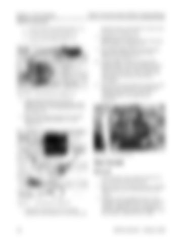
Figure 8- 10.
Encoder Bearing as Shipp ed in Kit
5. Install the bearing housing (P/N 00590-46054-71jon the mounting plate with four screws (P/N 00590-03113-71). See Figure 8-9.
11. Route the wires through the clamps on the top deck then back over and down the wiring channel to PS1 on the steer controller card. Use cable ties as necessary.
6. Remove the snap ring from the encoder bearing (P/N 00590-46055-71). See Figure 8-10.
Figure 8- 12.
Top of Steer Motor
Steer Encoder Removal 1. Turn the drive unit counter clockwise to the steering mechanical stops. 2. Remove the two mounting screws securing the encoder cover to the top of the steer motor. Figure 8- 1 1 .
Kit Components for Steps 7-9
7. Install the bearing into the housing oriented so the harness is on the top end.
3. Thread a 10-32 machine screw (1.5 in. long) into the tapped hole in the top of the encoder. Tighten the screw against the encoder shaft and continue to tighten until the encoder is lifted from the shaft.
00700-CL222-05, 1 5 March 2005


