8206code.fm Page 171 Tuesday, July 7, 1998 11:57 AM
DIAGNOSTIC CODE 7-6 Test 16 Checking for a pin-to-pin short in the harness
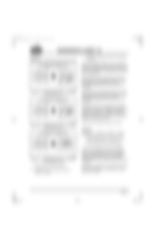
3. Check for continuity on the J1A connector, as follows: Check for continuity between J1A connector pin K1 (the rack position sensor signal [+] line) and each of the other pins (one at a time) on the J1A, J1B and J2 connectors, except pins K2 and J3 on the J1A connector. Next, check for continuity between pin K2 (the rack position sensor signal [+] line) and each of the other pins (one at a time) on all the connectors except pins K1 and J3 on the J1A connector.
Figure 285 — Continuity between Pin K1 and All Other Pins Except K2 and J3
Finally, check for continuity between pin J3 (the rack position sensor signal [+] line) and each of the other pins (one at a time) on all the connectors except pins K1 and K2 on the J1A connector.
If there is continuity with another pin, Deutsch connector pin A, E or F is shorted to ground in the harness or connector, or there is a pin-to-pin short in the harness or connector. Locate and repair the short to ground. Retest to be sure the problem has been corrected. If there is no continuity, proceed to Test 32. Figure 286 — Continuity between Pin K2 and All Other Pins Except K1 and J3
Test 32 Checking for a defective V-MAC II module 1. With the ignition key in the OFF position, reconnect the V-MAC II connectors. 2. Turn the ignition key to the ON position.
Figure 287 — Continuity between Pin J3 and All Other Pins Except K1 and K2
1. Disconnect the serial link jumper. 2. Disconnect the J2 connector from the V-MAC II module.
If code 7-6 is still active, check the V-MAC II module and connector for dirt, loose or broken pins, or repairable damage. If no repairable conditions are evident, replace the V-MAC II module. Retest to be sure the problem has been corrected. If code 7-6 is not active, the procedure has fixed the problem. Inspect all connectors to ensure proper connections.
Page 171


