1 minute read
SYMPTOM RELATED DIAGNOSTICS


BUFFERED RPM (continued)
Test 4
Checking for voltage on the buffered RPM line in the harness
1.Connect the serial link jumper into the serial communication port.
2.Measure the voltage from the buffered RPM line on the harness side of the tachometer connector.
If the voltage is greater than 0.5 volts, the buffered RPM line is shorted to voltage in the harness or connector. Locate and repair the short. Retest to be sure the problem has been corrected.
If the voltage is less than 0.5 volts, proceed to Test 8.
Test 8
Checking for a pin-to-pin short or a short to ground in the harness
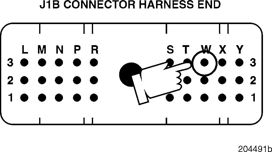
Test 16
Checking for an open in the harness
1.Disconnect the serial link jumper.
2.Check for pin-to-pin continuity between J1B connector pin W3 and each of the other pins (one at a time) on the J1A, J1B and J2 connectors.
If there is continuity with another pin, the buffered RPM line is shorted to ground in the harness or at the connectors. Locate and repair the short. Retest to be sure the problem has been corrected.
If there is no continuity, proceed to Test 16.
1.Connect a jumper between J1B connector pins W3 and P1.
2.Check for continuity from the buffered RPM line, on the harness side of the tachometer connector, to a good ground.
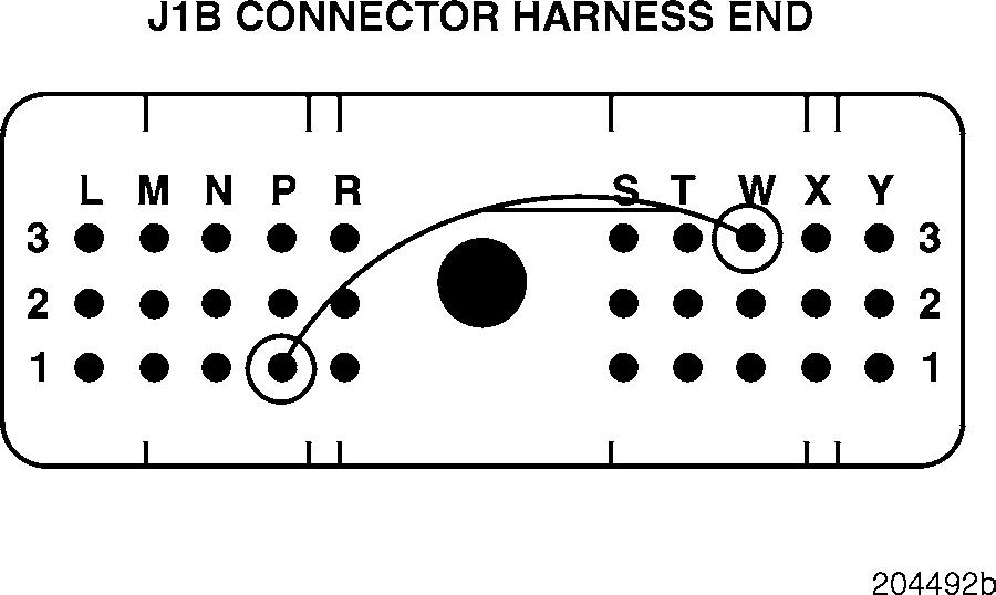
If there is continuity, proceed to Test 32.
If there is no continuity, the buffered RPM line is open in the harness. Locate and repair the open. Retest to be sure the problem has been corrected.
Test 32
Checking for proper voltage to the tachometer when the engine is running
1.Remove the jumper between J1B connector pins P1 and W2.
2.Reconnect the J1B connector.
3.Turn the ignition key to the ON position.
4.Measure the voltage from the buffered RPM line on the tachometer connector while the engine is running.
If the voltage is between 1.75 and 3.25 volts, proceed to Test 64.
If the voltage is not within this range, replace the V-MAC II module. Retest to be sure the problem has been corrected.
Page 199


