24 minute read
DIAGNOSTIC CODE 1-7


Checking for a failed sensor
1.Replace the coolant level sensor.
2.Reconnect the J1A, J1B, and J2 connectors.
3.Turn the ignition key to the ON position.
If code 1-7 is active, proceed to Test 64.
If code 1-7 is no longer active, replacing the sensor has corrected the problem.
Test 64
Checking for a damaged connector
1.Turn the ignition key to the OFF position.
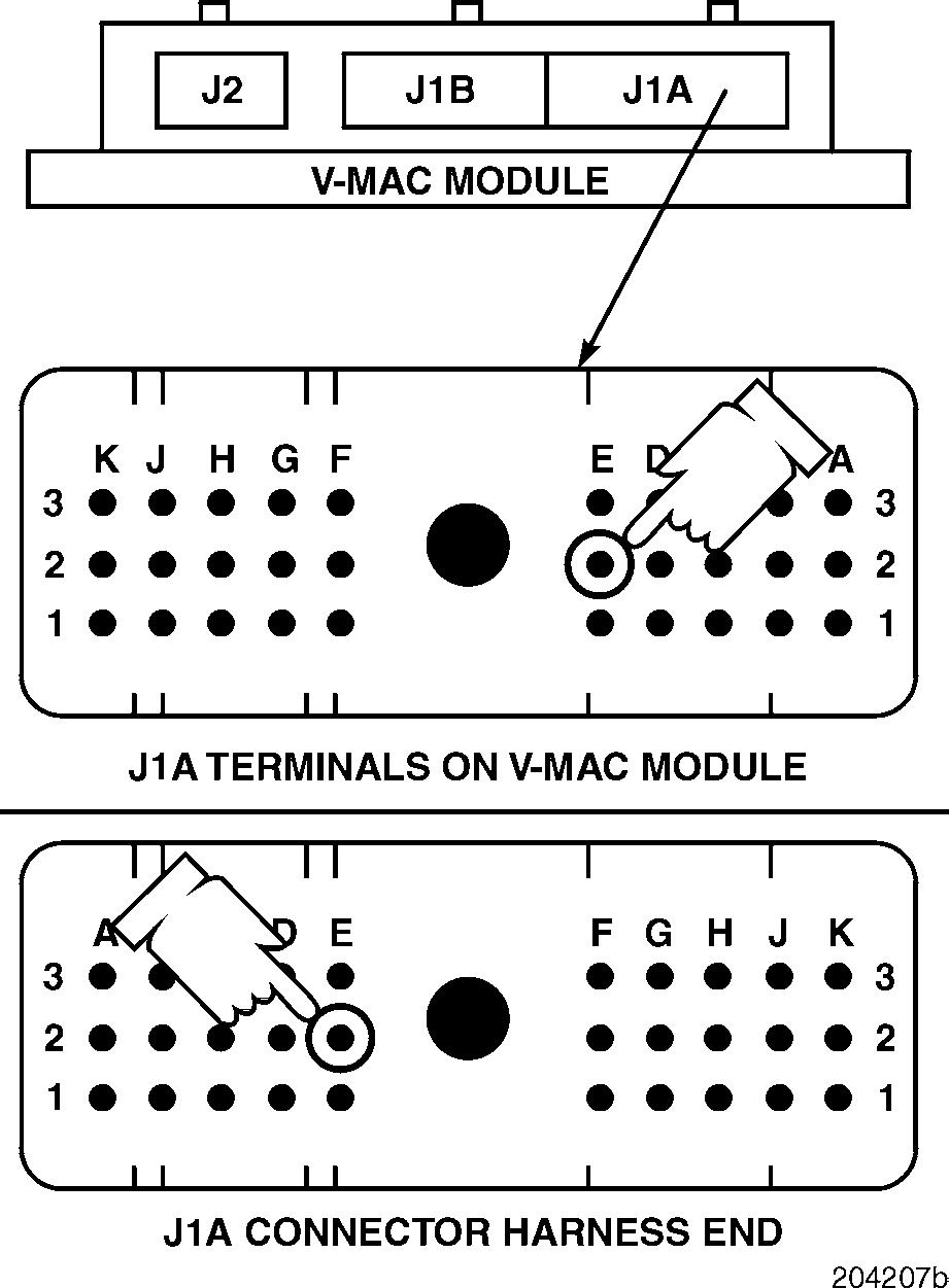
2.Disconnect the J1A connector from the V-MAC II module.
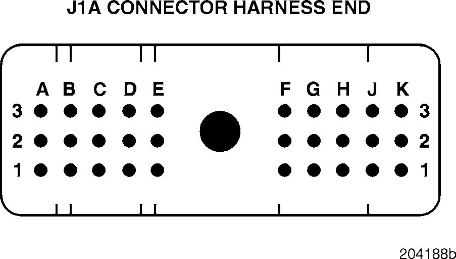
3.Visually inspect for damaged, broken or missing pins on the J1A connector.
If damage is evident, repair or replace the J1A connector (if possible).
If there is no evidence of damage, reconnect the circuit and turn the ignition key to the ON position. If the fault is still present, replace the V-MAC II module. If the fault is not present, the procedure has corrected the problem. Clean and inspect the connections.
DIAGNOSTIC CODE 1-8
DIAGNOSTIC BLINK CODE 1-8
Starter Input Tests
When performing electrical tests, it is important to wiggle wires and connectors to identify intermittent connection problems.
This fault becomes active if the engine is running and the input voltage to the starter relay remains high. This fault will not become active until the engine is running. If the fault is active and the engine stops, the fault will become inactive.
This fault will not become active if the starter relay becomes stuck in the engaged position unless the key is also in the start position.
Test 1
DIAGNOSTIC CODE 1-8
Checking the ignition position
1.Turn the ignition key to the ON position.
If the starter engages, proceed to Test 2.
If the starter does not engage, proceed to Test 3.
Test 2
Checking the diode
Some chassis do not have a connection via a diode between the starter and the accessory relay. If there is no provision in the wiring for this diode, proceed to Test 5.
1.Turn the ignition key to the OFF position.
2.Remove the diode, located on the electrical equipment panel, which connects wire J2-A3-0.8 (from the starter) to wire J1B-R3-0.8 (from the accessory relay).
3.Turn the ignition key to the ON position.
If the starter engages, proceed to Test 5.
If the starter does not engage, the diode is shorted. Replace the diode. Retest to be sure the problem has been corrected.
Test 3
Checking switch status
1.With the ignition key still in the ON position, check the switch status of the starter input (Aux 3 input) using a diagnostic tool (Pro-Link or PC).
If the diagnostic tool indicates that the starter is ON, proceed to Test 6.
If the diagnostic tool indicates that the starter is OFF, proceed to Test 7.
Test 5
Checking for a push-button start switch
1.Turn the ignition key to the OFF position.
2.Locate and disconnect the connector for the optional push-button start switch, which is attached to wire J1B-M3-0.8 (from the ignition switch).
If the vehicle uses a push-button start switch, proceed to Test 10.
If the vehicle does not use a push-button start switch, proceed to Test 11.
Test 6
DIAGNOSTIC CODE 1-8
Checking for a short to voltage
Test 7
Confirming the fault
1.Start the engine.
If after several minutes code 1-8 does not become active, the problem may be intermittent in nature and hard to diagnose. The fault may have been caused by accidental engagement of the starter. Determine, from the customer, the conditions that existed when the code became active in order to duplicate the conditions.
If code 1-8 becomes active, proceed to Test 14.
Figure 56 — Voltage from Pin A3 to Ground
1.Turn the ignition key to the OFF position.
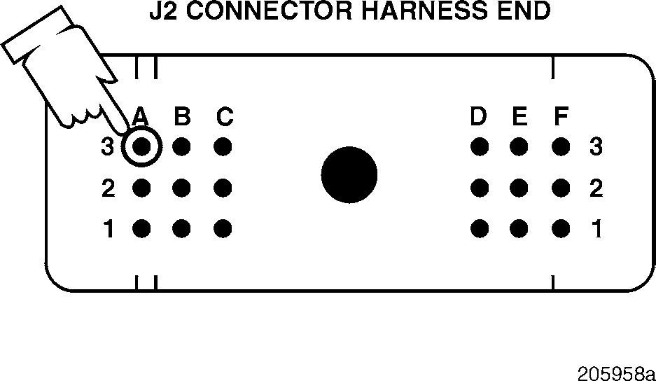
2.Disconnect the J2 connector from the V-MAC II module.
3.Turn the ignition key to the ON position.
4.Measure the voltage from J2 connector pin A3 (the starter signal [+] line) to a good ground.
If the voltage is greater than 5 volts, there is a short to voltage on wire J2-A3-0.8. Locate and repair the short. Since the starter is not engaged, it is also possible that there is a break in the same wire before it reaches the starter relay. Once the short to voltage is repaired, check the switch status when the starter is engaged. If the switch status indicated that the starter (Aux 3) is not engaged, there is also an open in the wire. Locate and repair the open. Retest to be sure the problem has been corrected.
If the voltage is less than 5 volts, proceed to Test 12.
Test
10
Checking for a faulty push-button start switch
1.Remove the push-button start switch from the harness connector.
2.With the button in the OFF position, check for continuity between pins A and B of the push-button start switch.
If there is continuity, replace the push-button start switch. Retest to be sure the problem has been corrected.
If there is no continuity, there is a short in the harness between wire J2-A3-0.8 and 12 volts. Locate and repair the short.
DIAGNOSTIC CODE 1-8
Test 11
Checking for a faulty switch
1.Turn the ignition key to the ON position.
2.Disconnect the push-button start bypass connector.
3.Measure the voltage from pin B (wire 2-D-0.8), on the key switch side of the push-button start bypass connector, to a good ground.
If 12 volts are present, the key switch is shorted internally. Replace the key switch. Retest to be sure the problem has been corrected.
If 12 volts are not present, continue with the next step.
4.With the push-button start bypass connector still disconnected, measure the voltage from pin B (wire J2-A3-0.8) on the circuit side of the connector to a good ground.
If 12 volts are present, there is a short to power in the harness between wire J2-A3-0.8 and 12 volts. Locate and repair the short. Retest to be sure the problem has been corrected.
If 12 volts are not present, the circuit is functioning properly and the problem is somewhere else in the system. Retest to be sure the problem has been corrected.
Test 12
Checking for a defective connector
1.Visually inspect the J2 connector on both the module and harness sides for bent pins, contamination or corrosion or any other cause of a short.
If there is a repairable condition, repair the connector. Retest to be sure the problem has been corrected.
If there is not a repairable condition, continue with the next step.
2.Clean the connector, reconnect the module and check the switch status with a diagnostic tool (Pro-Link or PC).
If the diagnostic tool indicates the correct starter status, the procedures have corrected the problem. Check all connectors to ensure proper connections.
If the diagnostic tool indicates that the starter is ON when it is not, replace the V-MAC II module. Retest to be sure the problem has been corrected.
Test 14
Checking for an intermittent short
1.With the engine running and code 1-8 still active, disconnect the J2 connector from the V-MAC II module.
If code 1-8 becomes inactive, there is an intermittent short to voltage on wire J2-A3-0.8. Locate and repair the short. Then continue with the next step.
If code 1-8 does not become inactive, replace the V-MAC II module. Retest to be sure the problem has been corrected.
Since the starter is not engaged, it is also possible that there is also a break in this same wire before it reaches the starter relay.
2.Once the short to voltage is repaired, check the switch status when the starter is engaged using a diagnostic tool (Pro-Link or PC).
If the switch status indicates that the starter (Aux 3 input) is not engaged, there is also an open in the wire. Locate and repair the open. Retest to be sure the problem has been corrected.
DIAGNOSTIC BLINK CODE 2-1 OR 2-2
COOLANT TEMPERATURE SENSOR TESTS
When performing electrical tests, it is important to wiggle wires and connectors to identify intermittent connection problems.
Blink Code 2-12-2
PID 110110
SID
FMI 43
MID 142 142
Name Engine Coolant Temperature Engine Coolant Temperature
DIAGNOSTIC CODE 2-1 OR 2-2 Page
Voltage above normal or shorted high
Test 1
DIAGNOSTIC CODE 2-1 OR 2-2
Checking sensor resistance
1.Check for continuity from either lead (pin A or pin B) of the sensor to a good ground.
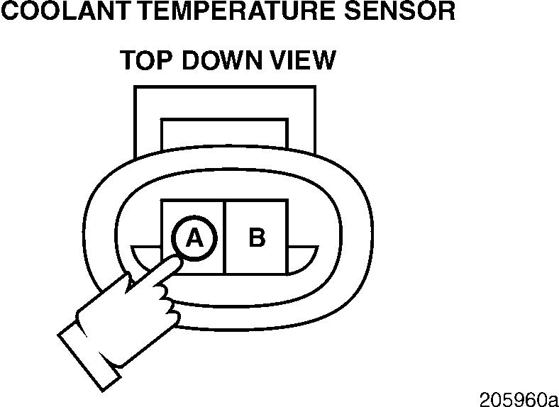
If there is continuity, replace the sensor. Retest to be sure the problem has been corrected. If there is no continuity, proceed to Test 4.
Test 3
Checking the signal line for voltage
1.Turn the ignition key to the OFF position.
2.Disconnect the coolant temperature sensor from the harness.
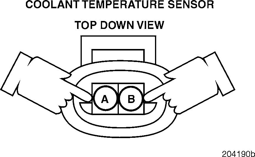
3.Measure the resistance between harness connector pins A (the signal [+] line) and B (the ground [ ] line) with the coolant temperature between 0 and 90 °C (32 and 94°F).
If the resistance is between 200 and 9400 ohms, proceed to Test 2.
If the resistance is not between 200 and 9400 ohms, proceed to Test 3.
Test 2
Checking for a short to ground in the sensor
1.Turn the ignition key to the ON position.
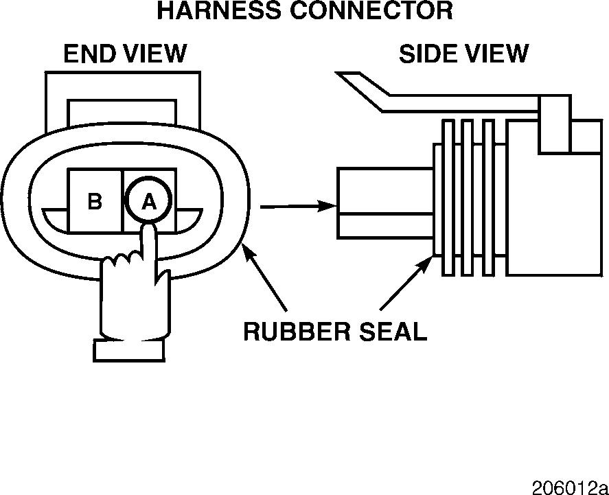
2.Measure the voltage from harness connector pin A (the signal [+] line) to a good ground.
If the voltage is greater than 6 volts, proceed to Test 6.
If the voltage is less than 6 volts, visually inspect the sensor connector for a repairable short or open. If there is a repairable condition, locate and repair the short or open on the sensor. If there is not a repairable condition, replace the sensor. Retest to be sure the problem has been corrected.
Test 4
DIAGNOSTIC CODE 2-1 OR 2-2
Checking for proper supply voltage to the sensor
1.Turn the ignition key to the OFF position.
2.Disconnect the J1A, J1B and J2 connectors from the V-MAC II module.
3.Connect the serial link jumper into the serial communication port.
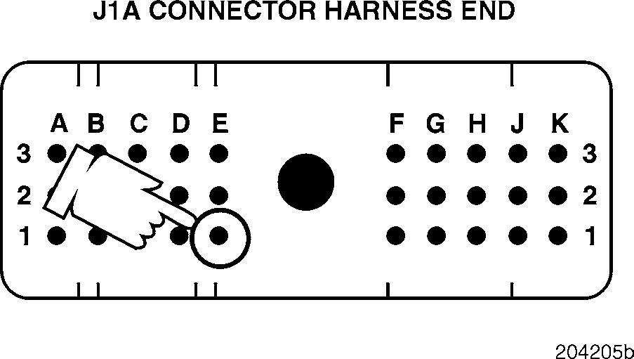
4.Measure the voltage from J1A connector pin E1 (the coolant temperature [+] line) to a good ground.
If the voltage is greater than 6 volts, the signal line is shorted to voltage somewhere the harness. Locate and repair the short, and replace the sensor. Retest to be sure the problem has been corrected.
If there is no voltage indicated, proceed to Test 12.
1.Turn the ignition key to the ON position.
2.Measure the voltage from harness connector pin A (the signal [+] line) to a good ground.
If the voltage is between 4.5 and 5.5 volts, proceed to Test 8.
If the voltage is not within this range, proceed to Test 9.
Test 6
Checking for a short to 12 volts on the signal line
Test 8
Checking for proper voltage on the ground terminal on the sensor side of the connector
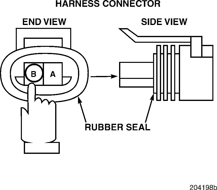
1.Measure the voltage from harness connector pin B (the ground [+] line) to a good ground.
If the voltage is greater than 0.5 volts, proceed to Test 17.
If the voltage is less than 0.5 volts, proceed to Test 16.
Test 9
DIAGNOSTIC CODE 2-1 OR 2-2
Checking for a short in the harness between the V-MAC II module and the sensor
Test 12
Checking for a short in the V-MAC II connector
1.Turn
2.Disconnect
3.Connect a jumper between J1A connector pins E1 and E2.
4.Check for continuity between harness connector pins A (the signal [+] line) and B (the ground [ ] line).
If there is continuity, proceed to Test 18.
If there is no continuity, there is an open in the signal line in the harness, on the harness side of the sensor connector or on the J1A connector. Locate and repair the open. Retest to be sure the problem has been corrected.
1.Disconnect the serial link jumper.
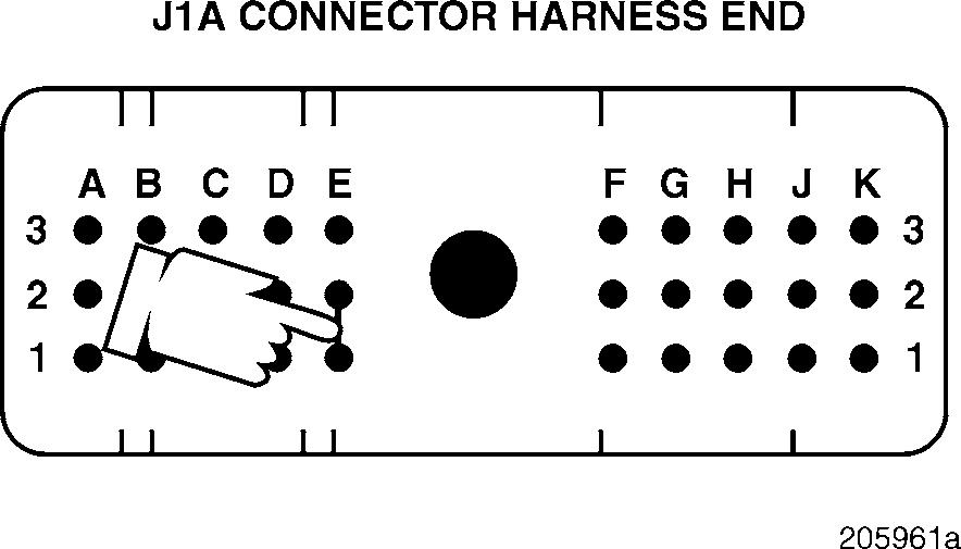
2.Check for continuity between J1A connector pin E1 (the coolant temperature [+] line) and each of the other pins (one at a time) on the J1A, J1B and J2 connectors.
If there is continuity with another pin, there is a short between pin E1 and the line which showed continuity in the harness. Locate and repair the short, and replace the sensor. Retest to be sure the problem has been corrected.
If there is no continuity, proceed to Test 24.
Test 16
DIAGNOSTIC CODE 2-1 OR 2-2
Checking for continuity to ground on the ground line in the harness
Test 17
Checking for an external short to voltage on the ground line
1.Turn the ignition key to the OFF position.
2.Check for continuity from harness connector pin B (the ground [ ] line) to a good ground.
If there is continuity, proceed to Test 32.
If there is no continuity, proceed to Test 33.
1.Turn the ignition key to the OFF position.
2.Disconnect the J1A, J1B and J2 connectors from the V-MAC II module.
3.Connect the serial link jumper into the serial communication port.
4.Measure the voltage from harness connector pin B (the ground [ ] line) to a good ground.
If the voltage is greater than 0.5 volts, there is a short in the ground line in the harness, on the sensor connector harness side, or on the J1A connector. Locate and repair the short, and replace the V-MAC II module. Retest to be sure the problem has been corrected.
If the voltage is less than 0.5 volts, proceed to Test 34.
Test 18
DIAGNOSTIC CODE 2-1 OR 2-2
Checking for an external voltage short to the signal line in the harness
Test 24
Checking for a defective connector or V-MAC II module
1.Remove the
2.Disconnect the J1B and J2 connectors from
3.Connect the serial link jumper into the serial communication port.
4.Measure the voltage from J1A connector pin E1 (the coolant temperature [+] line) to a good ground.
If the voltage is greater than 0.5 volts, the signal line is shorted to voltage in the harness, or on the harness side of the sensor or J1A connector. Locate and repair the short. Retest to be sure the problem has been corrected.
If the voltage is less than 0.5 volts, proceed to Test 36.
1.Visually inspect the coolant temperature sensor harness connector for a short between pin A and a 12-volt supply, and the J1A connector for a short between pin E1 and a 12-volt supply.
If there is a repairable short, repair the short and replace the sensor. Retest to be sure the problem has been corrected.
If there is not a repairable short, replace the sensor and the J1A connector or V-MAC II module. Retest to be sure the problem has been corrected.
Test 32
DIAGNOSTIC CODE 2-1 OR 2-2
Checking for an external short to voltage on the signal line in the harness
1.Disconnect the J1A, J1B and J2 connectors from the V-MAC II module.
2.Connect the serial link jumper into the serial communication port.
3.Measure the voltage from J1A connector pin E1 (the coolant temperature [+] line) to a good ground.
If the voltage is greater than 0.5 volts, the signal line is shorted in the harness, or on the harness side of the sensor connector or the J1A connector. Locate and repair the short. Retest to be sure the problem has been corrected.
If the voltage is less than 0.5 volts, proceed to Test 64.
Test 33
Checking for an open in the ground line in the harness
1.Turn the ignition key to the OFF position.
2.Disconnect the J1A connector from the V-MAC II module.
3.Connect a jumper between J1A connector pins E1 and E2.
4.Check for continuity between harness connector pins A (the signal [+] line) and B (the ground [ ] line).
If there is continuity, proceed to Test 66.
If there is no continuity, there is an open in the ground line in the harness or on the harness side of the connector. Locate and repair the open. Retest to be sure the problem has been corrected.
If the coolant temperature fault (code 2-1 or 2-2) is not accompanied by an air temperature fault (code 2-3 or 2-4), the open in the ground line is near the sensor, somewhere after the ground line breaks of the common ground with the air temperature sensor. If there is also an air temperature fault, the open is farther back in the harness.
Test 34
DIAGNOSTIC CODE 2-1 OR 2-2
Checking for a pin-to-pin short in the harness
1.Disconnect the serial link jumper.
2.Check for continuity from J1A connector pin E1 (the coolant temperature [+] line) to a good ground.
If there is continuity, the signal line is shorted to ground in the harness or on the J1A connector. Locate and repair the short. Retest to be sure the problem has been corrected.
If there is no continuity, proceed to Test 72.
Test 64
Checking for a pin-to-pin short on the signal line in the harness
1.Disconnect the serial link jumper.
2.Check for continuity between J1A connector pin E2 (the coolant temperature [ ] line) and each of the other pins (one at a time) on the J1A, J1B and J2 connectors.
If there is continuity with another pin, the ground line is shorted to voltage in the harness or in the connector. Locate and repair the short and replace the V-MAC II module. Retest to be sure the problem has been corrected.
If there is no continuity, proceed to Test 68.
Test 36
Checking for a short to ground in the signal line in the harness
1.Disconnect the serial link jumper.
2.Check for continuity between J1A connector pin E1 (the coolant temperature [+] line) and each of the other pins (one at a time) on the J1A, J1B and J2 connectors.
If there is continuity with another pin, there is a 5-volt pin-to-pin short in the signal line in the harness. Locate and repair the short. Retest to be sure the problem has been corrected.
If there is no continuity, proceed to Test 128.
Test 66
Checking for an open in the V-MAC connector
Test 68
Checking for a defective sensor connection
1.Visually inspect both sides of the J1A connector for an open around pin E2. If there is a repairable open, locate and repair the open. Retest to be sure the problem has been corrected.
If there is not a repairable open, replace the V-MAC II module or J1A connector. Retest to be sure the problem has been corrected.
1.Remeasure the resistance across the two leads of the sensor (pins A and B) with the coolant temperature between 0 and 90 °C (32 and 194°F).
2.Connect the coolant temperature sensor to the harness.
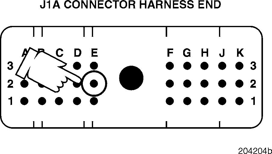
3.Measure the resistance between J1A connector pins E1 (the coolant temperature [+] line) and E2 (the coolant temperature [ ] line).
If the resistance is within 20 ohms of the resistance across the bare sensor (step 1 above), proceed to Test 136.
If the resistance is not within 20 ohms of the resistance across the bare sensor, there is an open on the sensor connector, or (less likely) at the bulkhead connector. Locate and repair the open. Retest to be sure the problem has been corrected.

Test 72
DIAGNOSTIC CODE 2-1 OR 2-2
Checking for a pin-to-pin short in the harness
Test 128
Checking for an open in the sensor connector
1.Check for continuity between J1A connector pin E1 (the coolant temperature [+] line) and each of the other pins (one at a time) on the J1A, J1B and J2 connectors.
If there is continuity with another pin, the signal line is shorted to ground in the sensor connector or one of the V-MAC connectors. Locate and repair the short. Retest to be sure the problem has been corrected.
If there is no continuity, proceed to Test 144.
1.Remeasure the resistance across the two leads of the sensor (pins A and B) with the coolant temperature between 0 and 90 ° C (32 and 194°F).
2.Reconnect the coolant temperature sensor.
3.Measure the resistance between J1A connector pins E1 (the coolant temperature [+] line) and E2 (the coolant temperature [ ] line).
If the resistance is within 20 ohms of the resistance across the bare sensor (step 1 above), proceed to Test 256.
If the resistance is not within 20 ohms of the resistance across the bare sensor, there is an open in the sensor connector, or (less likely) at the bulkhead connector. Locate and repair the open. Retest to be sure the problem has been corrected.
DIAGNOSTIC CODE 2-1 OR 2-2
Test 136
Checking for a short in the V-MAC II connectors
1.With the ignition key in the OFF position, reconnect the V-MAC II connectors.
2.Turn the ignition key to the ON position.
If blink code 2-1 or 2-2 is still active, check the V-MAC II module and connectors for dirt, loose or broken pins, or repairable damage. If no repairable conditions are evident, replace the V-MAC II module. Retest to be sure the problem has been corrected.
If blink code 2-1 or 2-2 is not active, the procedures have corrected the problem. Check all connectors to ensure proper connections.
Test 144
Checking for an open or short in the V-MAC II connectors
1.With the ignition key in the OFF position, reconnect the V-MAC II connectors.
2.Turn the ignition key to the ON position.
If blink code 2-1 or 2-2 is still active, check the V-MAC II module and connector for dirt, loose or broken pins, or repairable damage. If no repairable conditions are evident, replace the V-MAC II module. Retest to be sure the problem has been corrected.
If blink code 2-1 or 2-2 is not active, the procedures have corrected the problem. Check all connectors to ensure proper connections.
Test 256
Checking for a defective V-MAC II module or a loose connector
1.With the ignition key in the OFF position, reconnect the V-MAC II connectors.
2.Turn the ignition key to the ON position.
If blink code 2-1 or 2-2 is still active, check the V-MAC II module and connector for dirt, loose or broken pins, or repairable damage. If no repairable conditions are evident, replace the V-MAC II module. Retest to be sure the problem has been corrected.
If blink code 2-1 or 2-2 is not active, the procedures have corrected the problem. Check all connectors to ensure proper connections.
Test 1
DIAGNOSTIC CODE 2-3 OR 2-4
Checking sensor resistance
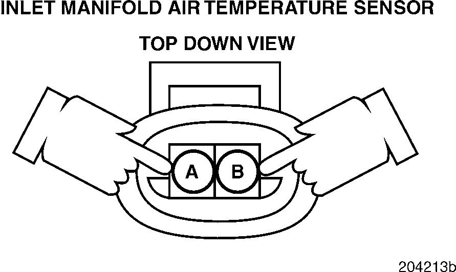
1.Check for continuity from either lead of the sensor (pin A or B) to a good ground.
If there is continuity, replace the sensor. Retest to be sure the problem has been corrected. If there is no continuity, proceed to Test 4.
Test 3
Checking the signal line for voltage
1.Turn the ignition key to the OFF position.
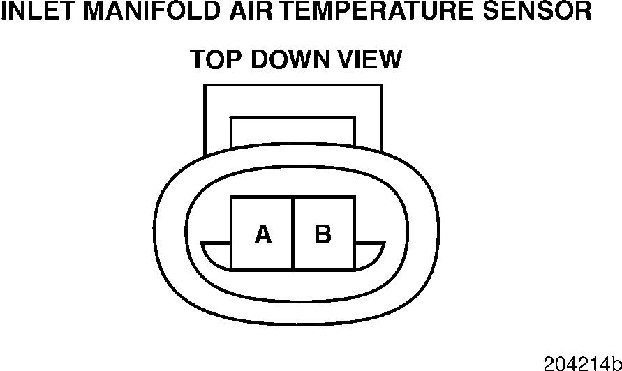
2.Disconnect the intake manifold temperature sensor from the harness.
3.Measure the resistance across the two leads of the sensor (pins A and B) with the intake manifold temperature between 0 and 90 °C (32 and 194°F).
If the resistance is between 200 and 9400 ohms, proceed to Test 2.
If the resistance is not between 200 and 9400 ohms, proceed to Test 3.
Test 2
Checking for a short to ground in the sensor
1.Turn the ignition key to the ON position.
2.Measure the voltage from harness connector pin A (the signal [+] line) to a good ground.
If the voltage is greater than 6 volts, proceed to Test 6.
If the voltage is less than 6 volts, visually inspect the sensor connector for a repairable short or open. If there is a repairable condition, locate and repair the short or open on the sensor. If there is not a repairable condition, replace the sensor. Retest to be sure the problem has been corrected.
Test 4
DIAGNOSTIC CODE 2-3 OR 2-4
Checking for proper supply voltage to the sensor
Test 6
Checking for a short to 12 volts on the signal line
1.Turn the ignition key to the ON position.
2.Measure the voltage from harness connector pin A (the signal [+] line) to a good ground.
If the voltage is between 4.5 and 5.5 volts, proceed to Test 8.
If the voltage is not within this range, proceed to Test 9.
1.Turn the ignition key to the OFF position.
2.Disconnect the J1A and J1B connectors from the V-MAC II module.
3.Connect the serial link jumper into the serial communication port.
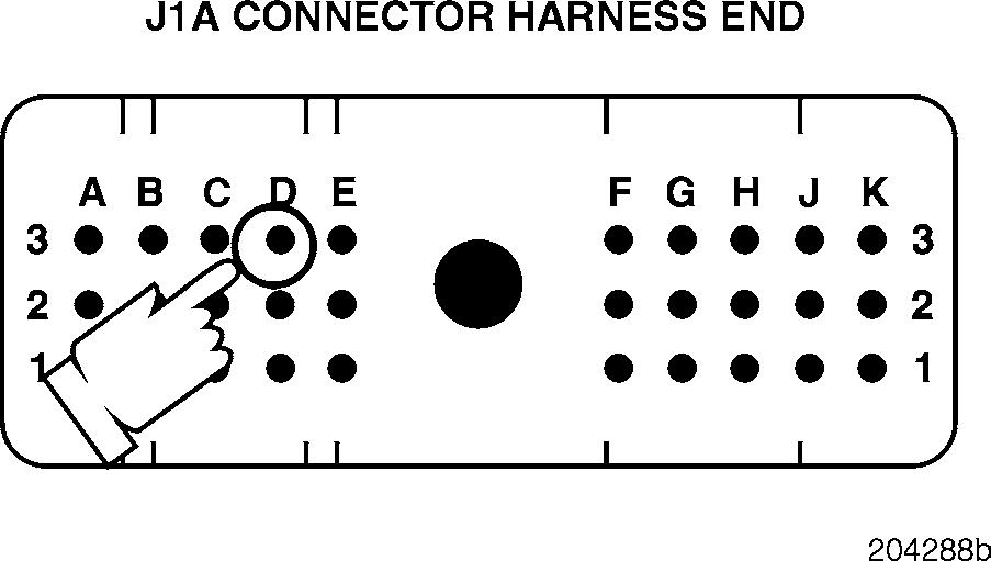
4.Measure the voltage from J1A connector pin D3 (the intake manifold temperature signal [+] line) to a good ground.
If the voltage is greater than 6 volts, the signal line is shorted to voltage somewhere in the harness. Locate and repair the short, and replace the sensor. Retest to be sure the problem has been corrected.
If there is no voltage indicated, proceed to Test 12.
Test 8
Checking for proper voltage on the ground line on the sensor side of the connector
Test 9
Checking for a short in the harness between V-MAC and the sensor
1.Measure the voltage from
If the voltage is greater than 0.5 volts, proceed to Test 17.
If the voltage is less than 0.5 volts, proceed to Test 16.
1.Turn the ignition key to the OFF position.
2.Disconnect the J1A connector from the V-MAC II module.
3.Connect a jumper between J1A connector pins D3 and E2.
4.Check for continuity between harness connector pins A (the signal [+] line) and B (the ground [ ] line), on the sensor side of the connector.
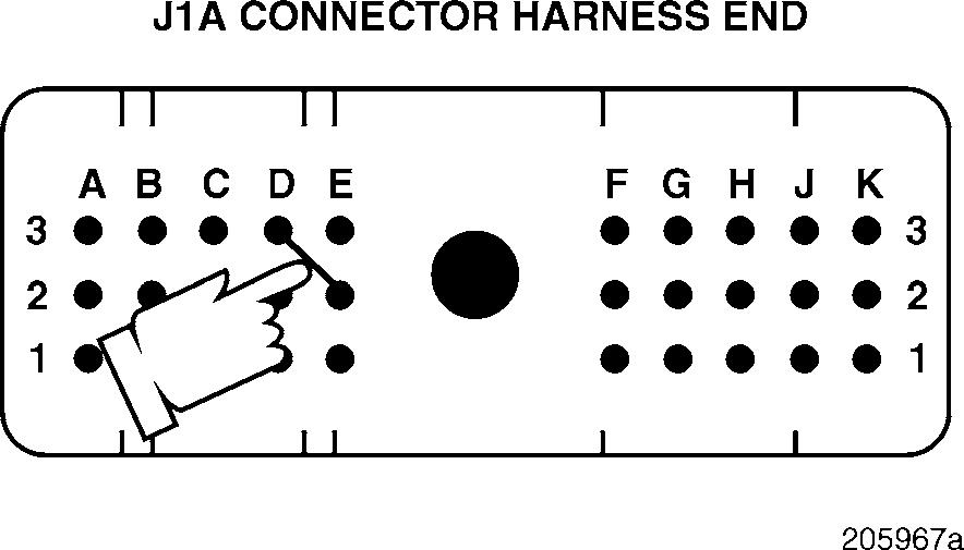
If there is continuity, proceed to Test 18.
If there is no continuity, there is an open in the signal line in the harness, on the harness side of the connector, or in the J1A connector. Locate and repair the open. Retest to be sure the problem has been corrected.
Test 12
DIAGNOSTIC CODE 2-3 OR 2-4
Checking for a short in the V-MAC II connector
Test 16
Checking for continuity to ground on the ground line in the harness
1.Disconnect the serial link jumper.
2.Disconnect the J2 connector from the V-MAC II module.
3.Check for continuity between J1A connector pin D3 (the intake manifold temperature signal [+] line) and each of the other pins (one at a time) on the J1A, J1B and J2 connectors.
If there is continuity with another pin, there is a short between pin D3 and the line which showed continuity in the harness. Locate and repair the short, and replace the sensor. Retest to be sure the problem has been corrected.
If there is no continuity, proceed to Test 24.
1.Turn the ignition key to the OFF position.
2.Check for continuity from harness connector pin B (the ground [ ] line) to a good ground.
If there is continuity, proceed to Test 32.
If there is no continuity, proceed to Test 33.
Test 17
DIAGNOSTIC CODE 2-3 OR 2-4
Checking for an external short to voltage on the ground line
Test 18
Checking for an external voltage short to the signal line in the harness
1.Turn the ignition key to the OFF position.
2.Disconnect the J1A and J1B connectors from the V-MAC II module.
3.Connect the serial link jumper into the serial communication port.
4.Measure the voltage from harness connector pin B (the ground [ ] line) to a good ground.
If the voltage is greater than 0.5 volts, there is a short in the ground line E2 in the harness, on the sensor connector harness side, or on the J1A connector. Locate and repair the short, and replace the V-MAC II module. Retest to be sure the problem has been corrected.
If the voltage is less than 0.5 volts, proceed to Test 34.
1.Remove the jumper between J1A connector pins D3 and E2.
2.Disconnect the J1B and J2 connectors from the V-MAC II module.
3.Connect the serial link jumper into the serial communication port.
4.Measure the voltage from J1A connector pin D3 (the intake manifold temperature signal [+] line) to a good ground.
If the voltage is greater than 0.5 volts, the signal line is shorted to voltage in the harness, or on the harness side of the sensor or J1A connector. Locate and repair the short. Retest to be sure the problem has been corrected.
If the voltage is less than 0.5 volts, proceed to Test 36.
Test 24
DIAGNOSTIC CODE 2-3 OR 2-4
Checking for a defective connector or V-MAC II module
Test 32
Checking for an external short to voltage on the signal line in the harness
1.Visually both
If there is a repairable short, repair the short and replace the sensor. Retest to be sure the problem has been corrected.
If there is not a repairable fault, replace the sensor and the J1A connector or V-MAC II module. Retest to be sure the problem has been corrected.
1.Disconnect
2.Connect the serial link jumper into the serial communication port.
3.Measure the voltage from J1A connector pin D3 (the intake manifold temperature signal [+] line) to a good ground.
If the voltage is greater than 0.5 volts, the signal line is shorted in the harness, or on the harness side of the sensor connector or the J1A connector. Locate and repair the short. Retest to be sure the problem has been corrected.
If the voltage is less than 0.5 volts, proceed to Test 64.
Test 33
DIAGNOSTIC CODE 2-3 OR 2-4
Checking for an open in the ground line in the harness
If the air temperature fault (code 2-3 or 2-4) is not accompanied by a coolant temperature fault (code 2-1 or 2-2), the open in the ground line is near the sensor, somewhere after the ground line breaks off of the common ground with the coolant temperature sensor. If there is also a coolant temperature fault, the open is farther back in the harness.
Test 34
Checking for a pin-to-pin short in the harness
1.Turn the ignition key to the OFF position.
2.Disconnect the J1A connector from the V-MAC II module.
3.Connect a jumper between J1A connector pins D3 and E2.
4.Check for continuity between harness connector pins A (the signal [+] line) and B (the ground [ ] line).
If there is continuity, proceed to Test 66. If there is no continuity, there is an open in the ground line E2 in the harness or on the harness side of the sensor connector. Locate and repair the open. Retest to be sure the problem has been corrected.
1.Disconnect the serial link jumper.
2.Disconnect the J2 connector from the V-MAC II module.
3.Check for continuity between J1A connector pin E2 (the coolant temperature [ ] line) and each of the other pins (one at a time) on the J1A, J1B and J2 connectors.
If there is continuity with another pin, the ground line (pin E2) is shorted to voltage in the harness or in the connector. Locate and repair the short and replace the V-MAC II module. Retest to be sure the problem has been corrected.
If there is no continuity, proceed to Test 68.
Test 36
DIAGNOSTIC CODE 2-3 OR 2-4
Checking for a short to the ground in the signal line in the harness
If there is continuity with another pin, there is a 5-volt pin-to-pin short in the signal line in the harness. Locate and repair the short. Retest to be sure the problem has been corrected.
If there is no continuity, proceed to Test 128.
Test 66
Checking for an open in the V-MAC II connector
1.Disconnect the serial link jumper.
2.Check for continuity from J1A connector pin
(the intake manifold temperature signal [+] line) to a good ground.
If there is continuity, the signal line is shorted to ground in the harness or on the J1A connector. Locate and repair the short. Retest to be sure the problem has been corrected.
If there is no continuity, proceed to Test 72.
Test 64
Checking for a pin-to-pin short to 5 volts on the signal line in the harness
1.Disconnect the serial link jumper.
2.Check for continuity between J1A connector pin D3 (the intake manifold temperature signal [+] line) and each of the other pins (one at a time) on the J1A, J1B and J2 connectors.
1.Visually inspect both sides of the J1A connector for an open around pin E2.
If there is a repairable open, locate and repair the open. Retest to be sure the problem has been corrected.
If there is not a repairable open, replace the V-MAC II module or J1A connector. Retest to be sure the problem has been corrected.
Test 68
Checking for a bad sensor connection
Test 72
Checking for a pin-to-pin short in the harness
1.Remeasure the resistance across the two leads of the sensor (pins A and B on the sensor) with the intake manifold temperature between 0 and 90°C (32 and 194°F).
2.Connect the intake manifold temperature sensor to the harness.
3.Measure the resistance between J1A connector pins D3 (the intake manifold temperature signal [+] line) and E2 (the coolant temperature [ ] line).
If the resistance is within 20 ohms of the resistance across the bare sensor (step 1 above), proceed to Test 136.
If the resistance is not within 20 ohms of the resistance across the bare sensor, there is an open in the sensor connector, or (less likely) at the bulkhead connector. Locate and repair the open. Retest to be sure the problem has been corrected.
1.Check for continuity between J1A connector pin D3 (the intake manifold temperature signal [+] line) and each of the other pins (one at a time) on the J1A, J1B and J2 connectors.
If there is continuity with another pin, the signal line is shorted to ground in the sensor connector or one of the V-MAC II connectors. Locate and repair the short. Retest to be sure the problem has been corrected.
If there is no continuity, proceed to Test 144.
DIAGNOSTIC CODE 2-3 OR 2-4
Test 128
Checking for an open in the sensor connector
Test 136
Checking for a short in the V-MAC II connector
1.With the ignition key in the OFF position reconnect the V-MAC II connectors.
2.Turn the ignition key to the ON position.
If blink code 2-3 or 2-4 is still active, check the V-MAC II module and connector for dirt, loose or broken pins, or repairable damage. If no repairable conditions are evident, replace the V-MAC II module. Retest to be sure the problem has been corrected.
If blink code 2-3 or 2-4 is not active, the procedures have corrected the problem. Check all connectors to ensure proper connections.
Test 144
Checking for an open or short in the V-MAC II connector
1.With the ignition key in the OFF position reconnect the V-MAC II connectors.
2.Turn the ignition key to the ON position.
1.Remeasure the resistance across the two leads of the sensor (terminals A and B on the sensor) with the intake manifold temperature between 0 and 90 °C (32 and 194°F).
2.Reconnect the intake manifold temperature sensor.
3.Measure the resistance between J1A connector pins D3 (the intake manifold temperature signal [+] line) and E2 (the coolant temperature [ ] line).
If the resistance is within 20 ohms of the resistance across the bare sensor (step 1 above), proceed to Test 256.
If the resistance is not within 20 ohms of the resistance across the bare sensor, there is an open in the sensor connector, or (less likely) at the bulkhead connector. Locate and repair the open. Retest to be sure the problem has been corrected.
If blink code 2-3 or 2-4 is still active, check the V-MAC II module and connector for dirt, loose or broken pins, or repairable damage. If no repairable conditions are evident, replace the V-MAC II module. Retest to be sure the problem has been corrected.
If blink code 2-3 or 2-4 is not active, the procedures have corrected the problem. Check all connectors to ensure proper connections.


