2 minute read
DIAGNOSTIC CODE 7-7


Checking for a change in blink code when the pump is disconnected
1.Turn the ignition key to the OFF position.
2.Disconnect the engine harness from the injection pump connector on the pump end of the harness.
3.Turn the ignition key to the ON position.
If the blink code changes from 7-7 to 7-5, proceed to Test 4.
A 5-3 code should also be present.
If the blink code does not change from 7-7 to 7-5, contact Service Engineering.
Test 4
Checking for an intermittent open or short in the wiring
1.Turn the ignition key to the OFF position.
2.Reconnect the engine harness to the injection pump connector on the pump end of the harness.
3.Turn the ignition key to the ON position.
4.Flex the engine harness from the bulkhead to the injection pump connector and the integral jumper harness.
If, at any time, the fault goes from active to inactive while flexing the harness, there is an intermittent rack position sensor open or short at that location in the harness. Contact Service Engineering before repairing the open or short.
If the fault does not go from active to inactive while flexing the harness, proceed to Test 8.
Test 8
Checking for intermittent contact at the pump
1.Turn the ignition key to the OFF position.
2.Disconnect the engine harness from the injection pump connector on the pump end of the harness.
3.Examine the connector pins for evidence of dirt, wear, foreign debris or intermittent contact.
If there is a repairable condition, repair as needed. Retest to be sure the problem has been corrected.
If there is no evidence of damage, proceed to Test 16.
Test 16
Checking for intermittent contact at the module
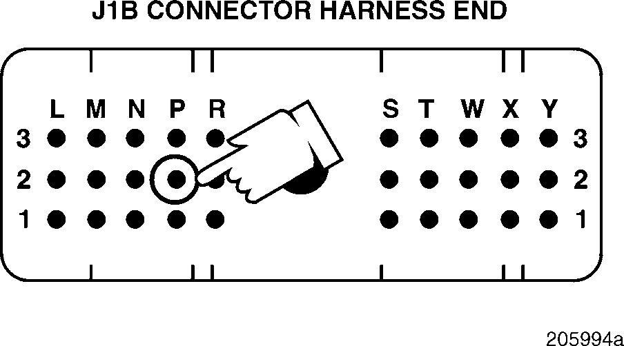
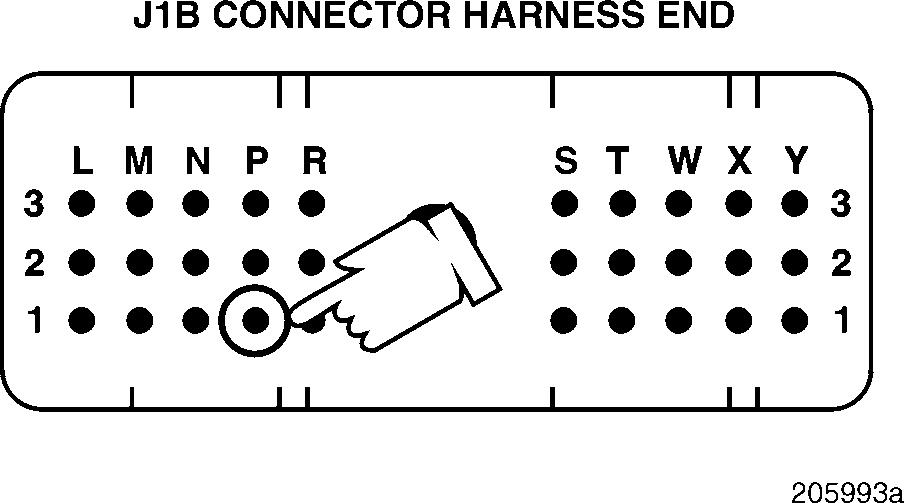
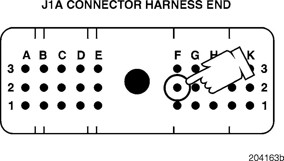
1.Disconnect the J1A and J1B connectors from the V-MAC II module.
2.Examine the connector pins for evidence of dirt, wear, foreign debris or intermittent contact.
If there is a repairable condition, repair as needed. Retest to be sure the problem has been corrected.
If there is no evidence of damage, proceed to Test 32.
Test 32
DIAGNOSTIC CODE 7-7
Checking for good ground connections
1.Turn off all electrical devices in the truck, including dome lights.
2.Check the resistance from each of the module ground wires (J1B connector pins P1 and P2 and J2 connector pin F2) to the negative battery post.
If the resistance to the battery post is greater than 1 ohm, clean the connections between the module and battery ground. Reconnect the J1A and J1B connectors to the V-MAC II module. Retest to be sure the problem has been corrected.
If the resistance is less than 1 ohm or the fault is still active, proceed to Test 64.
Test 64
Checking for good battery and alternator POSITIVE connections
1.Clean the battery and alternator POSITIVE connections. Retest to be sure the problem has been corrected.
If the fault is still active, contact Service Engineering.


