4 minute read
DIAGNOSTIC CODE 5-1


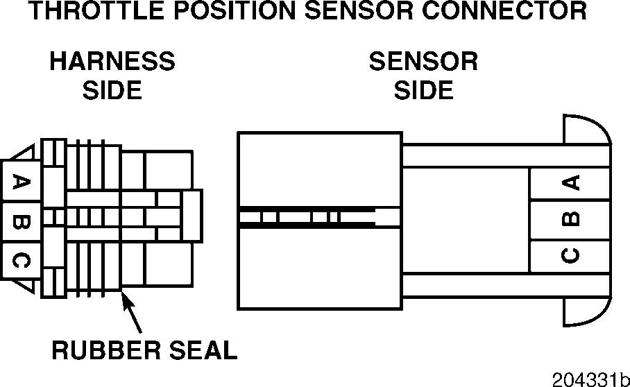
Checking for an open in the signal line in the harness
Test 5
Checking for continuity to ground on the signal line
1.Turn the ignition key to the OFF position.
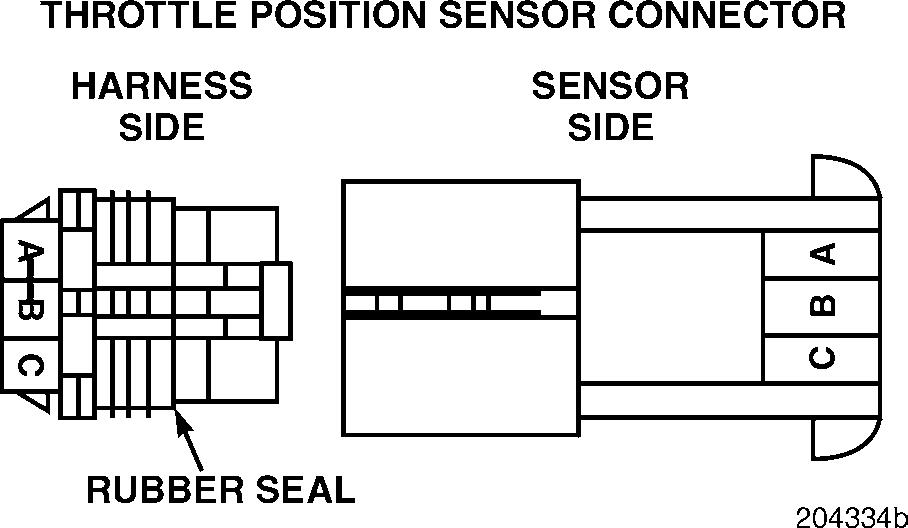
2.Connect a jumper between harness connector pins A and B, on the harness side of the connector.
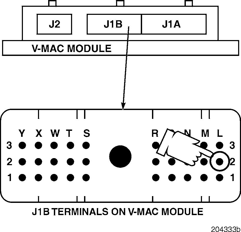
3.Disconnect the J1B connector from the V-MAC II module.
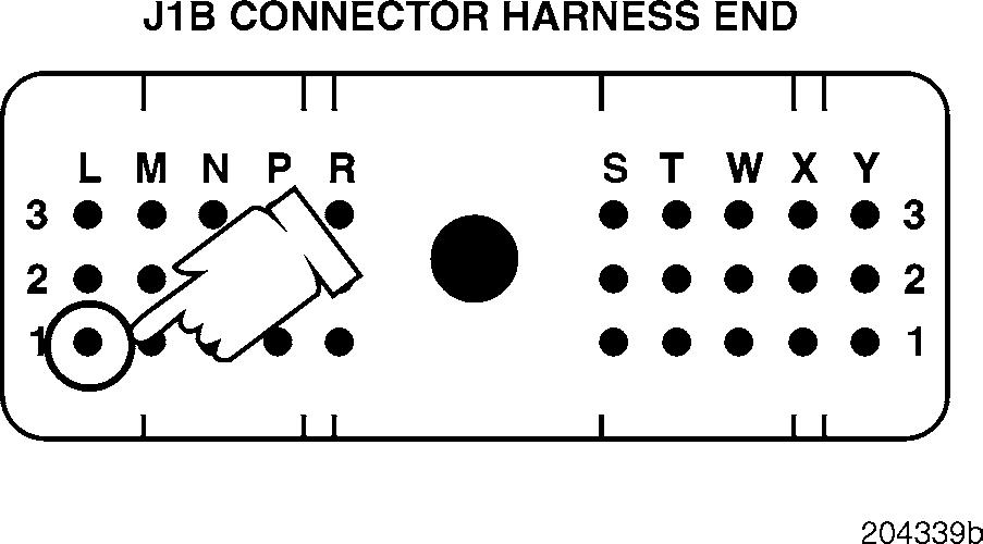
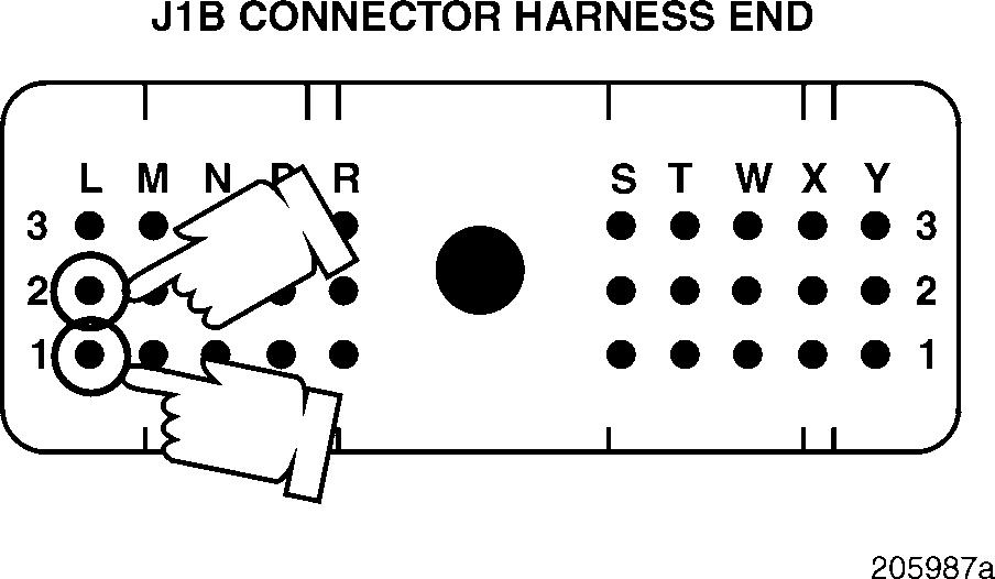
4.Check for continuity between J1B connector pins L1 (the TPS signal [+] line) and L2 (the TPS voltage reference [+] line).
If there is continuity, disconnect the jumper and proceed to Test 8.
If there is no continuity, locate and repair the open in the TPS signal line (pin L1) in the harness or connectors. Retest to be sure the problem has been corrected.
1.Turn the ignition key to the OFF position.
2.Disconnect the J1B connector from the V-MAC II module.
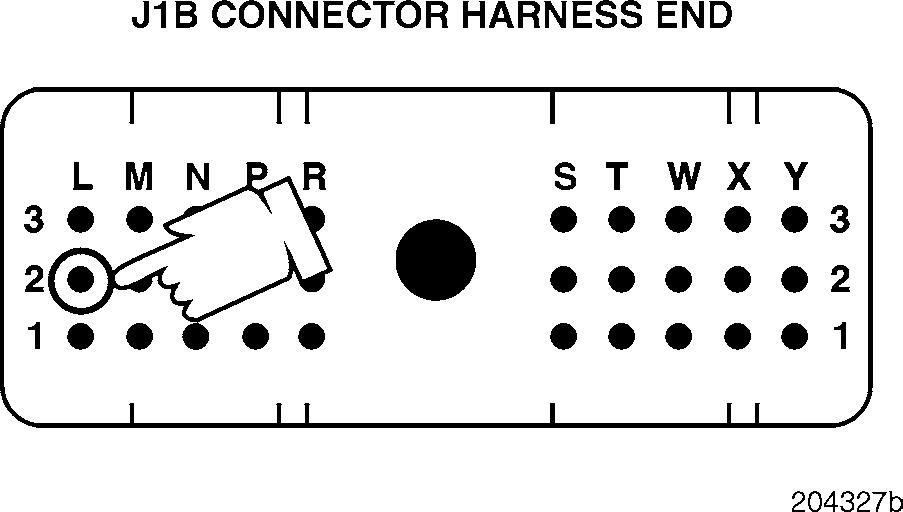
3.Check for continuity from J1B connector pin L1 (the TPS signal [+] line) to a good ground.
If there is continuity, locate and repair the short to ground in the signal line. Retest to be sure the problem has been corrected.
If there is no continuity, proceed to Test 10.
Test 6
DIAGNOSTIC CODE 5-1
Checking for a short to ground in the voltage PLUS (+) line
1.Turn the ignition key to the OFF position.
2.Remove the jumper between harness connector pins A and B.
3.Disconnect the J1A and J2 connectors from the V-MAC II module.
4.Check for continuity between J1B connector pin L1 (the TPS signal [+] line) and each of the other pins (one at a time) on the J1A, J1B and J2 connectors.
If there is continuity with another pin, locate and repair the short in the TPS signal line. Retest to be sure the problem has been corrected.
If there is no continuity, proceed to Test 16.
1.Turn the ignition key to the OFF position.
2.Disconnect the jumper from harness connector pin A to ground.
3.Check for continuity from J1B connector pin L2 (the TPS voltage reference [+] line) to a good ground.
If there is continuity, locate and repair the short to ground in the TPS voltage reference [+] line in the harness or connector. Retest to be sure the problem has been corrected.
If there is no continuity, proceed to Test 12.
Test 8
Checking for a pin-to-pin short in the harness
Test 10
Checking for a pin-to-pin short in the harness
1.Turn the ignition key to the OFF position.
2.Disconnect the J1A and J2 connectors from the V-MAC II module.
3.Check for continuity between J1B connector pin L1 (the TPS signal [+] line) and each of the other pins (one at a time) on the J1A, J1B and J2 connectors.
If there is continuity with another pin, locate and repair the short in the TPS signal line. Retest to be sure the problem has been corrected.
If there is no continuity, proceed to Test 20.
Test 12
Checking for a pin-to-pin short in the harness
5-1
1.Visually inspect both sides of the sensor connector for a repairable open in any of the pins.
If there is a repairable open, repair or replace the TPS connector. Retest to be sure the problem has been corrected.
If there is not a repairable open, continue with the next step.
2.Find the purple J 35616-4 male test lead from the J 38581 V-MAC jumper wire kit. Align the male test lead with one of the rectangular female pins in the connector. Gently push the test lead into the connector pin. Repeat this process for the remaining two female pins.
1.Turn the ignition key to the OFF position.
2.Disconnect the J1A and J2 connectors from the V-MAC II module.
3.Check for continuity between J1B connector pin L2 (the TPS voltage reference [+] line) and each of the other pins (one at a time) on the J1A, J1B and J2 connectors.
If there is continuity with another pin, locate and repair the short to the voltage reference [+] line in the harness or connector. Retest to be sure the problem has been corrected.
If there is no continuity, proceed to Test 24.
Test 16
Checking for a fault in the sensor connector
If any of the pins in the connector feel loose, repair or replace the connector. Retest to be sure the problem has been corrected.
If none of the pins in the connector feel loose, continue with the next step.
3.Find the purple J 35616-5 female test lead from the J 38581 V-MAC jumper wire kit. Align the female test lead with one of the rectangular male pins in the Throttle Position Sensor connector. Gently push the test lead over the pin. Repeat this process for the remaining two male pins.
If any of the pins in the sensor feel loose, replace the Throttle Position Sensor or the connector. Retest to be sure the problem has been corrected.
If none of the pins in the connector feel loose, proceed to Test 32.
Test 20
DIAGNOSTIC CODE 5-1
Checking for a repairable short on the V-MAC II module
Test 24
Checking for an open or short in the V-MAC II module connector
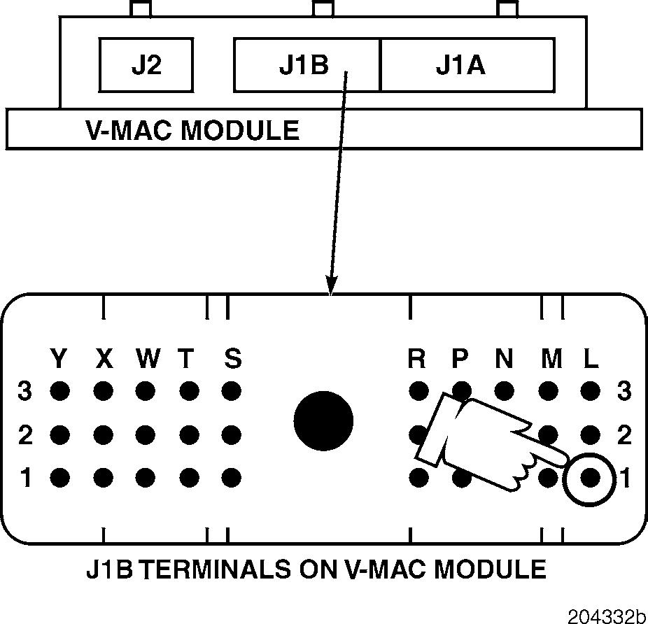
1.Visually inspect the module side of the J1B connector for a short between the TPS signal line pin L1 and all adjacent pins.
If there is a repairable short, repair the short in the connector on the TPS signal line. Retest to be sure the problem has been corrected.
If there is not a repairable short, replace the V-MAC II module. Retest to be sure the problem has been corrected.
1.Visually inspect the module side of the J1B connector for an open or short on pin L2 (the voltage reference [+] line).
If there is a repairable condition, repair the short or open in the V-MAC II module connector. Retest to be sure the problem has been corrected.
If there is not a repairable condition, reconnect the V-MAC II harnesses and the throttle position sensor connector. Turn the ignition key to the ON position. If the code 5-1 is still active, replace the V-MAC II module. If the fault is not active, check for loose connections in the sensor and module connectors. Retest to be sure the problem has been corrected.


