1 minute read
DIAGNOSTIC CODE 4-1, 4-2 OR 4-3


Test 26
Checking for continuity in the harness
Test 40
Checking for a pin-to-pin short
1.Disconnect the serial link jumper.
2.Disconnect the J2 connector from the V-MAC II module.
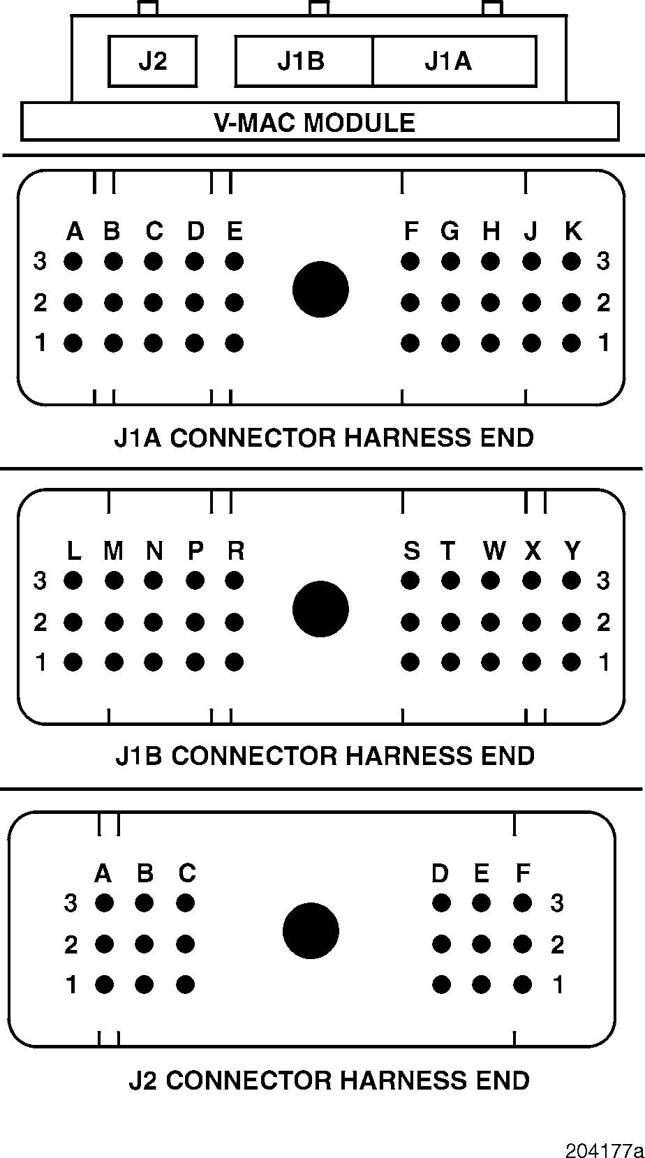
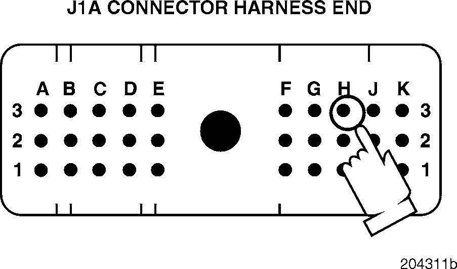
3.Check for continuity between J1A connector pin H3 (the MPH sensor PLUS [+] line) and each of the other pins (one at a time) on the J1A, J1B and J2 connectors.
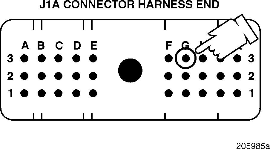
4.Check for continuity between J1A connector pin G3 (the MPH sensor MINUS [ ] line) and each of the other pins (one at a time) on the J1A, J1B and J2 connectors.
If there is continuity with another pin, repair the short in the harness between the pins which showed continuity. Retest to be sure the problem has been corrected.
If there is no continuity, replace the V-MAC II module. Retest to be sure the problem has been corrected.
1.Visually inspect the V-MAC II module and module connectors for pin-to-pin shorts.
If there are any shorts, locate and repair the short at the V-MAC II connectors. Retest to be sure the problem has been corrected.
If there are no repairable shorts, replace the V-MAC II module or connectors. Retest to be sure the problem has been corrected.
DIAGNOSTIC CODE 4-1, 4-2 OR 4-3
Test 48
Checking for a bad connection
1.Visually inspect both the harness and module sides of the V-MAC II module connectors for the cause of the open.
2.If no problem is found, clean the connector and reconnect the circuit.
If the problem no longer exists, check the connections at the sensor and module. Retest to be sure the problem has been corrected.
If the problem still exists, replace the V-MAC II module. Retest to be sure the problem has been corrected.
DIAGNOSTIC CODE 5-1
DIAGNOSTIC BLINK CODE 5-1
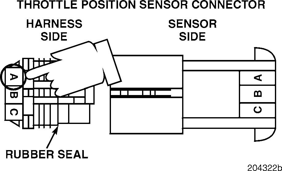
THROTTLE POSITION SENSOR (TPS) TESTS
When performing electrical tests, it is important to wiggle wires and connectors to identify intermittent connection problems.
Blink Code 5-1
PID 91
SID
FMI 4
MID 142
Name Throttle Position Sensor (TPS)
Failure Voltage below normal or shorted low
Test 1
Checking for proper voltage on the voltage PLUS (+) line
1.Turn the ignition key to the OFF position.
2.Disconnect the TPS from the harness.
3.Turn the ignition key to the ON position.
4.Measure the voltage from harness connector pin A (the voltage reference [+] line), on the sensor end of the connector, to a good ground.
If the voltage is greater than 4.35 volts, proceed to Test 2.
If the voltage is less than 4.35 volts, proceed to Test 3.
Page 111


