2 minute read
DIAGNOSTIC CODE 6-5


Checking for loose pins or a defective V-MAC II module
1.Turn the ignition key to the OFF position.
2.Disconnect the J1B connector from the V-MAC II module.
3.Visually inspect J1B connector pins N1, N2, N3, P1 and P2 for dirt, loose pins or deformed contacts.
4.Find the gray J 35616-2 male test lead from the J 38581 V-MAC jumper wire kit. Align the male test lead with J1B connector pin N1 and gently push the test lead into the connector pin. Repeat this process for J1B connector pins N2, N3, P1 and P2 (one at a time).
If there is a repairable open or terminals feel loose, repair or replace the J1B connector. Retest to be sure the problem has been corrected.
If the test lead is making good contact with the J1B connector pins, there is a problem somewhere else in the electrical system. Locate and repair the problem. Retest to be sure the problem has been corrected.
Test 32
Checking the code
1.Turn the ignition key to the OFF position.
2.Connect the J1B connector to the V-MAC II module.
3.Turn the ignition key to the ON position.
If code 6-5 is still active, replace the V-MAC II module. Retest to be sure the problem has been corrected.
If code 6-5 is not active, the procedures have corrected the problem. Check all connectors to ensure proper connections.
DIAGNOSTIC CODE 6-6
DIAGNOSTIC BLINK CODE 6-6
Internal Communications Tests
When performing electrical tests, it is important to wiggle wires and connectors to identify intermittent connection problems.
Test 1
Checking for adequate voltage out of the accessory relay
1.Turn the ignition key to the ON position.
2.Measure the voltage from the output of the accessory relay going to the electrical equipment panel to a good ground.
If the voltage is greater than 11 volts, or after correcting the low voltage problem the fault becomes active, proceed to Test 2.
This diagnostic determines if an internal V-MAC II module failure has occurred. The fault must be active when performing this procedure. The fault could be logged if there is insufficient voltage to the module.
If the voltage is less than 11 volts, the active fault may be caused by insufficient voltage at the module. Check battery and accessory relay connections, ground connections, and proper accessory relay operation. If a problem is found and corrected, cycle the key for 5 seconds and check for an active fault again. Retest to be sure the problem has been corrected.
Test 2
DIAGNOSTIC CODE 6-6
Checking for a damaged module connector
1.Turn the ignition key to the OFF position.
2.Disconnect the J1A, J1B and J2 module connectors from the V-MAC II module.
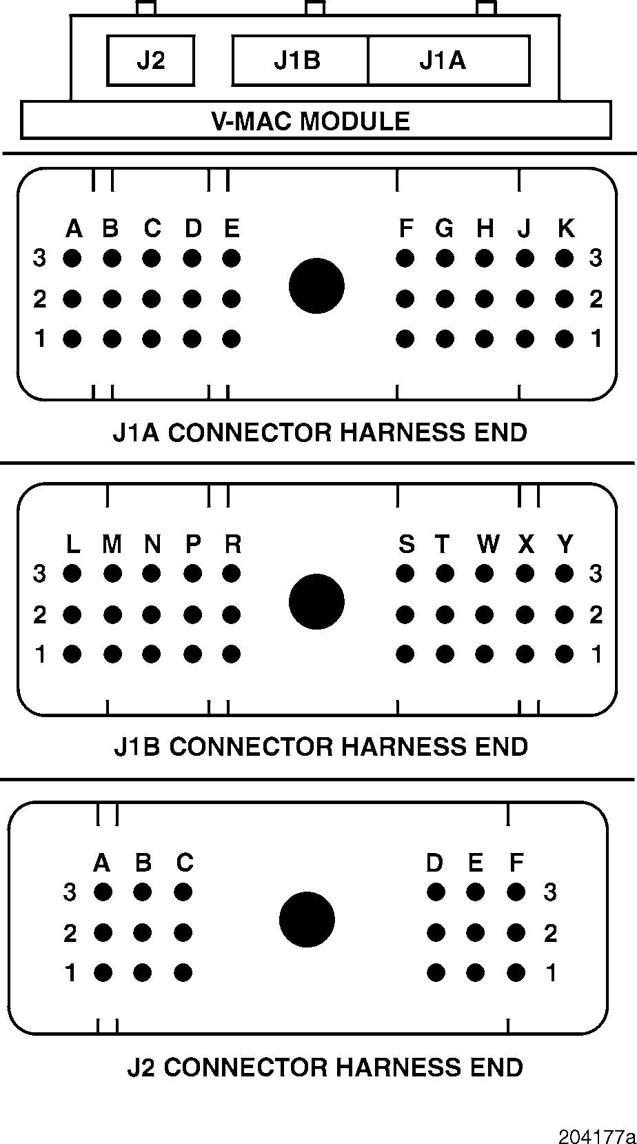
3.Visually inspect the harness and module sides of the V-MAC II module connectors to see if a repairable fault exists.
If there is a repairable fault, clean or repair the connector. Reconnect. Retest to be sure the problem has been corrected.
If there is not a repairable fault, replace the V-MAC II module or connectors. Retest to be sure the problem has been corrected.
DIAGNOSTIC CODE 7-1
DIAGNOSTIC BLINK CODE 7-1
SERVICE BRAKE SWITCH TESTS
When performing electrical tests, it is important to wiggle wires and connectors to identify intermittent connection problems.
Blink Code 7-1
PID
SID 246
FMI 4
MID 142
Name Brake Pedal Switch #1 (Service Brake)
Failure Voltage below normal or shorted low
This fault becomes active when V-MAC II detects a large and sudden decrease in vehicle speed while in cruise or speed control modes without a service brake signal input.
If this fault becomes active while on a chassis dynamometer, make the fault go inactive by applying the service brake for 1 second. Using a diagnostic tool (Pro-Link or PC), activate the Chassis Dynamometer Mode and rerun the dynamometer test. Once the test is completed, turn the ignition key to the OFF position for 3 seconds to restore the standard operating mode.