1 minute read
DIAGNOSTIC CODE 7-6


Checking for a pin-to-pin short in the harness
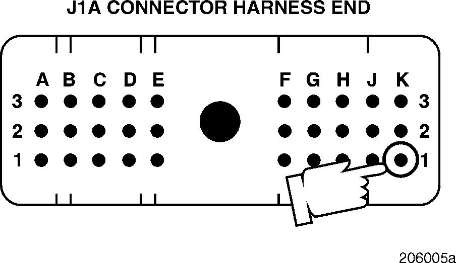
3.Check for continuity on the J1A connector, as follows:
Check for continuity between J1A connector pin K1 (the rack position sensor signal [+] line) and each of the other pins (one at a time) on the J1A, J1B and J2 connectors, except pins K2 and J3 on the J1A connector.
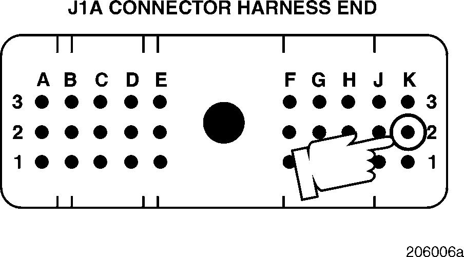
Next, check for continuity between pin K2 (the rack position sensor signal [+] line) and each of the other pins (one at a time) on all the connectors except pins K1 and J3 on the J1A connector.
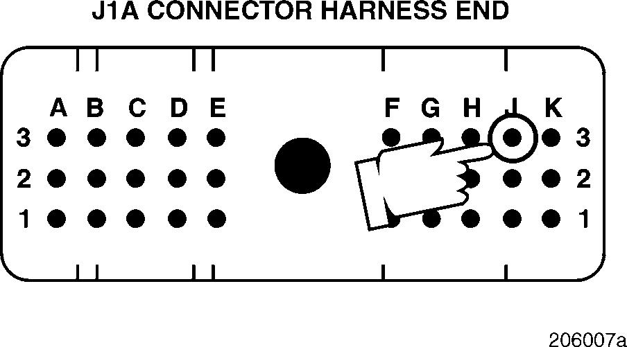
Finally, check for continuity between pin J3 (the rack position sensor signal [+] line) and each of the other pins (one at a time) on all the connectors except pins K1 and K2 on the J1A connector.
If there is continuity with another pin, Deutsch connector pin A, E or F is shorted to ground in the harness or connector, or there is a pin-to-pin short in the harness or connector. Locate and repair the short to ground. Retest to be sure the problem has been corrected.
If there is no continuity, proceed to Test 32.
Test 32
Checking for a defective V-MAC II module
1.With the ignition key in the OFF position, reconnect the V-MAC II connectors.
2.Turn the ignition key to the ON position.
If code 7-6 is still active, check the V-MAC II module and connector for dirt, loose or broken pins, or repairable damage. If no repairable conditions are evident, replace the V-MAC II module. Retest to be sure the problem has been corrected.
If code 7-6 is not active, the procedure has fixed the problem. Inspect all connectors to ensure proper connections.
DIAGNOSTIC CODE 7-7
DIAGNOSTIC BLINK CODE 7-7 RACK POSITION SENSOR TESTS
When performing electrical tests, it is important to wiggle wires and connectors to identify intermittent connection problems.
Test 1
Checking for adequate voltage out of the accessory relay
1.Turn the ignition key to the ON position.
2.Measure the voltage from the output of the accessory relay going to the electrical equipment panel to a good ground.
If the voltage is greater than 11 volts, or after correcting the low voltage problem the fault becomes active, proceed to Test 2.
An unexpected failure has occurred in the rack position system. This fault could be logged if there is insufficient voltage to the module.
If the voltage is less than 11 volts the active fault may be caused by insufficient voltage at the module. Check battery and accessory relay connections, ground connections, and proper accessory relay operation. If a problem is found and corrected, cycle the key for 5 seconds and check for an active fault again.