1 minute read
SYMPTOM RELATED DIAGNOSTICS


ENGINE BRAKE VERBAL COMPLAINT (continued)
Test 5
Checking for proper connections inside the cylinder head cover
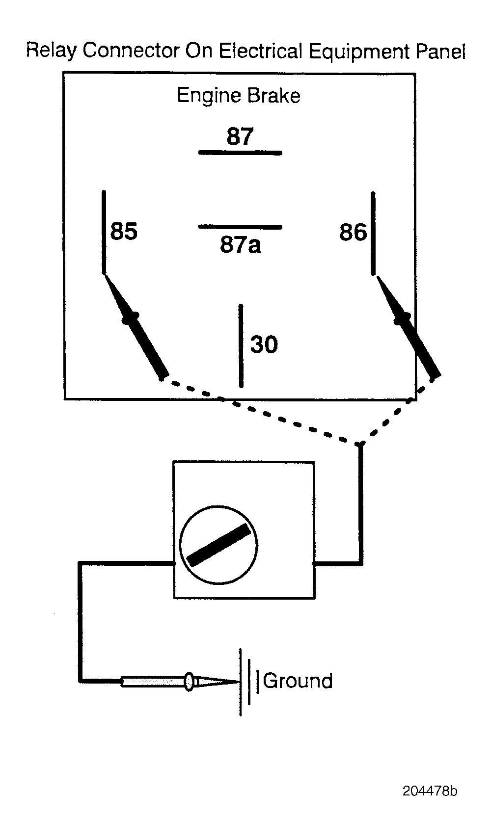
Test 8
Checking for continuity through the switch
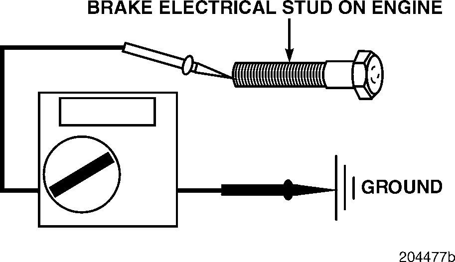
1.Disconnect the engine harness from the brake electrical studs on the engine. Do not disconnect any wires which connect together the brake solenoids on different heads (jumper wires between heads are used with Dynatard).
2.Measure the resistance from the engine brake electrical studs on the cylinder heads to a good ground.
If the resistance is within the range specified in the table below, reconnect the engine harness to the head and proceed to Test 10.
If the resistance is not within this range, there is a bad electrical connection in one of the heads, or in one of the brake solenoids, or a bad solenoid ground.
Resistance Ranges (in Ohms)
E7 DynatardE9 DynatardJacobs Dual Relay Jacobs Single Relay
*4–6*2–39.7–14.3*4.8–7.2
*If the resistance is double the specified range, the wire that connects the front and rear heads, or the left and right banks on the E9, may be open or has a bad connection.
1.Turn the engine brake switch on the dashboard to the ON position. If the switch controls more than one brake relay, turn the switch so that all of the relays will be energized.
2.Check for continuity from pin 85, on the brake relay connector, to a good ground.
3.Check for continuity from pin 86, on the brake relay connector, to a good ground.
Page 191


