6 minute read
DIAGNOSTIC CODE 5-7 OR 5-8


Checking the V-MAC II module
1.Turn the ignition key to the OFF position.
2.Reconnect the J1B connector.
3.Turn the ignition key to the ON position.
If code 5-7 becomes active, check the V-MAC II module for dirt. loose or broken pins or repairable damage. If no problems are evident, replace the V-MAC II module. Retest to be sure the problem has been corrected.
If code 5-7 is not active, the procedures have corrected the problem. Check all connectors to ensure proper connections.
DIAGNOSTIC CODE 5-9 OR 5-10
DIAGNOSTIC BLINK CODE 5-9 OR 5-10 ELECTRONIC
When performing electrical tests, it is important to wiggle wires and connectors to identify intermittent connection problems.
The electronic malfunction lamp will be unable to provide a diagnostic blink code while fault 5-9 or 5-10 is active.
If code 5-10 is active, the electronic malfunction lamp will be OFF and will remain OFF, even if a diagnostic code becomes active
DIAGNOSTIC CODE 5-9 OR 5-10
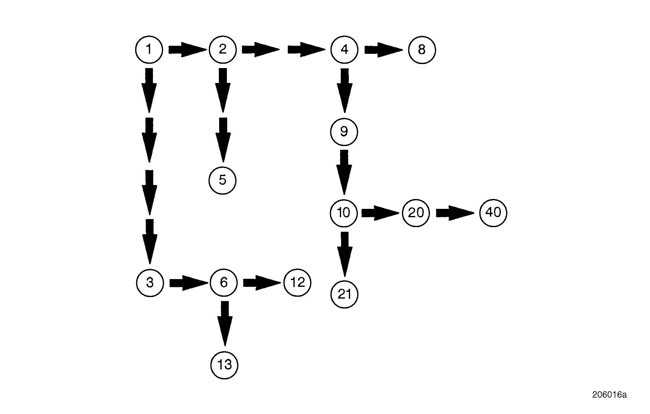
Test 1
Checking the code
1.Verify which code is active.
If code 5-9 is active, proceed to Test 2.
If code 5-10 is active, proceed to Test 3.
If neither code is active, wiggle the harness and connectors to try to activate the code. Visually inspect the connectors and instrument cluster for frayed, loose or corroded connections.
Test 2
Checking for a short to ground
1.Connect the Pro-Link 9000 or PC.
2.Turn the ignition key to the ON position.
If code 5-9 becomes active and the electronic malfunction lamp stays ON continuously, proceed to Test 4.
If code 5-9 becomes active but the electronic malfunction lamp does not stay ON continuously, proceed to Test 5.
If code 5-9 is inactive and the electronic malfunction lamp stays ON continuously, there is an intermittent short to ground on circuit J1B-R2-0.8. Wiggle the harness and connectors to try to make the fault active.
If code 5-9 is inactive and the electronic malfunction lamp comes ON for 2 seconds and then goes out, the system is functioning properly and the problem may be intermittent. Check connector at the V-MAC II module and instrument cluster for secure connections.
Test 3
Checking for continuous operation
This diagnostic procedure will detect a short to voltage only if the module is attempting to turn the electronic malfunction lamp ON.
1.Connect Pro-Link 9000 or PC.
2.Turn the ignition key to the ON position.
3.Disconnect the coolant level sensor. This will activate code 1-7 and cause the V-MAC II module to attempt to turn the electronic malfunction lamp ON.
4.After fault 1-7 has become active, reconnect the coolant level sensor.
5.Check the Active Fault Table (in Service Diagnostics) to see if code 5-10 is active.
If code 5-8 is active, proceed to Test 6.
If code 5-10 is not active, the problem may be intermittent and hard to diagnose. Check the connections at the shutdown lamp and driver alarm and J1B connector for a short to voltage.
Test 4
DIAGNOSTIC CODE 5-9 OR 5-10
Checking voltage at the V-MAC II module
Test 6
Checking for a short to voltage
1.Turn the ignition key to the OFF position.
2.Connect the serial link jumper into the serial communications port.
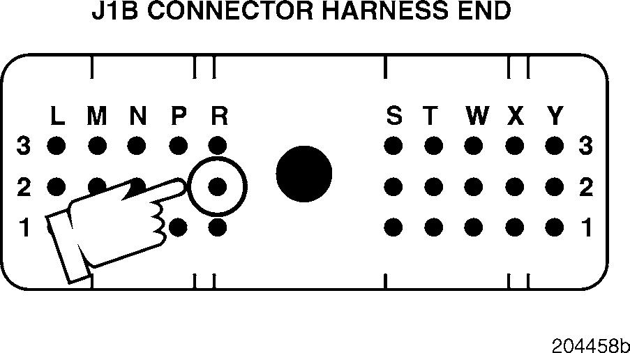
3.Measure the voltage from J1B connector pin R2 (the electronic malfunction lamp signal [+] line) to a good ground.
If battery voltage is present, proceed to Test 8.
If no voltage is present, proceed to Test 9.
Test 5
Checking the power supply circuit
Circuit 5-A-1.0 provides power to several gauges and indicators in the dash. An open or short to ground in this circuit may cause problems with these shared components. Some components powered by this circuit are: r Multi-purpose buzzer r Oil level indicator lamp r Malfunction indicator lamp r Parking brake warning lamp switch
If there are electrical problems with other components in the dash, there may be an open or short to ground in circuit 5-A-1.0. Locate and repair the open or short to ground. Retest to be sure the problem has been corrected.
If there are no other obvious electrical problems with components in the dash, proceed to Test 10.
1.Turn the ignition key to the OFF position.
2.Remove the electronic malfunction lamp bulb.
3.Disconnect the J1B connector from the V-MAC II module.
4.Connect the serial link jumper into the serial communications port.
5.Measure the voltage from J1B connector pin R2 (the electronic malfunction lamp signal [+] line) to a good ground.
If the voltage is greater than 0.5 volts, there is short to voltage. Proceed to Test 12.
If the voltage is less than 0.5 volts, proceed to Test 13.
Test 8
DIAGNOSTIC CODE 5-9 OR 5-10
Checking the V-MAC II module for a short
1.Disconnect the serial link jumper.
2.Disconnect the J1B connector from the V-MAC II module.
3.Visually inspect the J1B connector for dirt, loose or shorted pins or any other repairable condition.
If a repairable condition exists, repair the damage. Retest to be sure the problem has been corrected.
If there is not a repairable condition, replace the V-MAC II module or J1B connector. Retest to be sure the problem has been corrected.
Test 9
Short to ground isolation test
If there is another pin which shows continuity, J1B connector pin R2 is shorted to that pin. Locate and repair the short. Retest to be sure the problem has been corrected.
If there is no continuity, J1B connector pin R2 is shorted to ground somewhere else in the harness. Locate and repair the short to ground. Retest to be sure the problem has been corrected.
Test 10
Checking for an open
1.Turn the ignition key to the OFF position.
2.Remove the electronic malfunction lamp bulb.
3.Disconnect the J1A, J1B and J2 connectors from the V-MAC II module.
4.Check for continuity between J1B connector pin R2 (the electronic malfunction lamp signal [+] line) and each of the other pins (one at a time) on the J1A, J1B and J2 connectors.
1.Turn the ignition key to the OFF position.
2.Disconnect the J1B connector from the V-MAC II module.
3.Connect the serial link jumper into the serial communications port.
4.Measure the voltage from J1B connector pin R2 (the electronic malfunction lamp signal [+] line) to a good ground.
If battery voltage is present, proceed to Test 20.
If no voltage is present, check circuit J1B-R2-0.8 for an open. If circuit J1B-R2-0.8 is not faulty, proceed to Test 21.
DIAGNOSTIC CODE 5-9 OR 5-10
Test 12
Short to voltage isolation test
Test 13
Checking the V-MAC II module
1.Disconnect the serial link jumper.
2.Reconnect the J1B connector.
3.Install the electronic malfunction lamp bulb.
4.Turn the ignition key to the ON position.
5.Disconnect the coolant level sensor. This will activate code 1-7 and cause the V-MAC II module to attempt to turn the shutdown lamp ON.
1.Disconnect the serial link jumper.
2.Remove the electronic malfunction lamp bulb.
3.Disconnect the J1A, J1B and J2 connectors from the V-MAC II module.
4.Check for continuity between J1B connector pin R2 (the electronic malfunction lamp signal [+] line) and each of the other pins (one at a time) on the J1A, J1B and J2 connectors.
If there is another pin which shows continuity, J1B connector pin R2 is shorted to that pin. Locate and repair the short. Retest to be sure the problem has been corrected.
If there is no continuity, J1B connector pin R2 is shorted to voltage somewhere else in the harness. Locate and repair the short to voltage. Retest to be sure the problem has been corrected.
6.After fault 1-7 has become active, reconnect the coolant level sensor.
7.After 30 seconds, observe the electronic malfunction indicator and Active Fault Table (in Service Diagnostics) to see if the lamp remains ON and the fault 5-8 remains active.
If code 5-10 is active, check the V-MAC II module and connectors for a repairable condition. If no repairable condition is found, replace the V-MAC II module. Retest to be sure the problem has been corrected.
If code 5-10 is not active, the procedures have corrected the problem. Check all connectors to ensure proper connection.
Test 20
Checking J1B connector for an open
Test 21
Check supply voltage
1.Disconnect the serial link jumper.
2.Disconnect the J1B connector from the V-MAC II module.
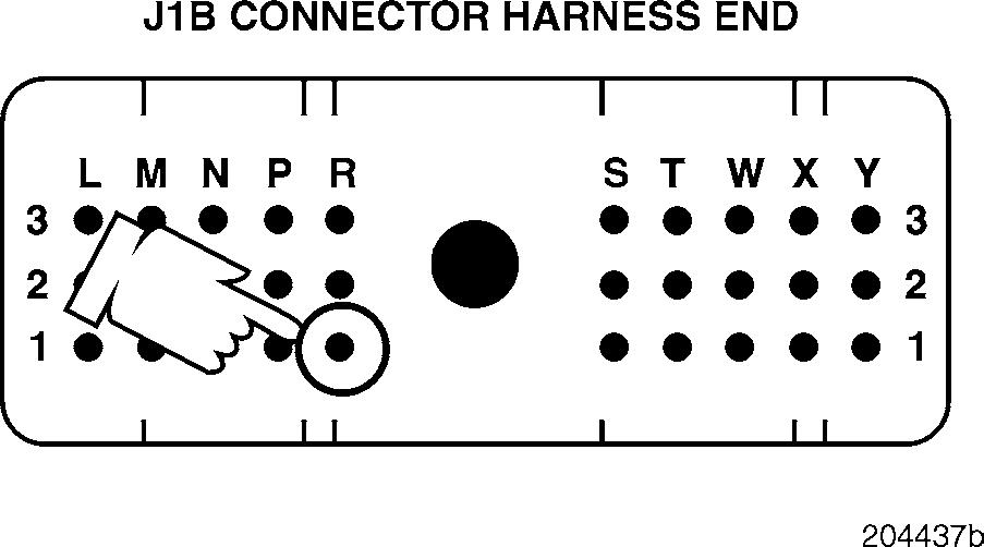
3.Visually inspect J1B connector pin R2 for dirt. loose pins or deformed contacts.
4.Align the J 35616-2 male test lead (found in the J 38581 V-MAC jumper wire kit) with J1B connector pin R1. Gently push the test lead into pin R2 and check for looseness.
If a repairable open is found or the terminal feels lose, repair the J1B connector. Retest to be sure the problem has been corrected.
If a repairable open is not found (the test lead is making good contact with J1B connector pin R2), proceed to Test 40.
1.Disconnect the serial link jumper.
2.Replace the electronic malfunction lamp bulb with a known good bulb.
3.Disconnect the J1B connector from the V-MAC II module.
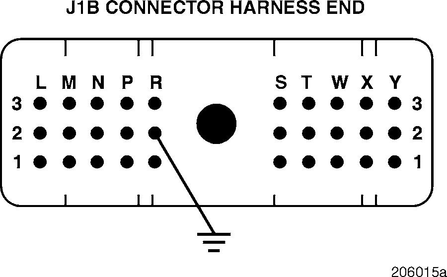
4.Connect a jumper from J1B connector pin R2 to a good ground.
5.Connect the serial link jumper into the serial communications port.
If the electronic malfunction lamp turns ON, the old bulb was faulty and replacing the bulb has corrected the problem.
If the electronic malfunction lamp still does not turn ON, there is an open in supply circuit 5-A-1.0. Locate and repair the open. Retest to be sure the problem has been corrected.


