15 minute read
INTRODUCTION


CHANGES FROM THE EXISTING V-MAC II SERVICE MANUAL
Mack Trucks, Inc. has made many improvements to this V-MAC II® Service Manual, with changes to both content and organization.
This updated service manual now covers additional diagnostic blink codes including: r 1-8 — Starter input (high voltage) r 5-7 — Driver alarm output (low voltage) r 5-8 — Driver alarm output (high voltage) r 5-9 — Fault lamp output (low voltage) r 5-10 — Fault lamp output (high voltage) r 6-5 — Battery voltage (low voltage)
The DESCRIPTION AND OPERATION section provides an overview of the V-MAC II system, as well as a brief description of each component.
The DIAGNOSTIC TOOLS AND PROCEDURES section outlines the diagnostic software and equipment that will be needed. It also provides troubleshooting procedures and service hints.
The BLINK CODE DIAGNOSTICS section includes step-by-step procedures for troubleshooting diagnostic blink codes.
The SYMPTOM RELATED DIAGNOSTICS section provides the troubleshooting procedures for situations where there is no diagnostic blink code.
The REPAIR AND ADJUSTMENT PROCEDURES section guides the technician through connector repair, clutch switch adjustment, sensor adjustment and resetting low idle speed.
The SPECIFICATIONS section provides engine parameters, while the SPECIAL TOOLS section includes a listing of the necessary tools.
The SAE MESSAGE DESCRIPTIONS section provides a list of SAE/ATA serial line codes and corresponding descriptions.
Table Of Contents
Table Of Contents
Description And Operation
General Information
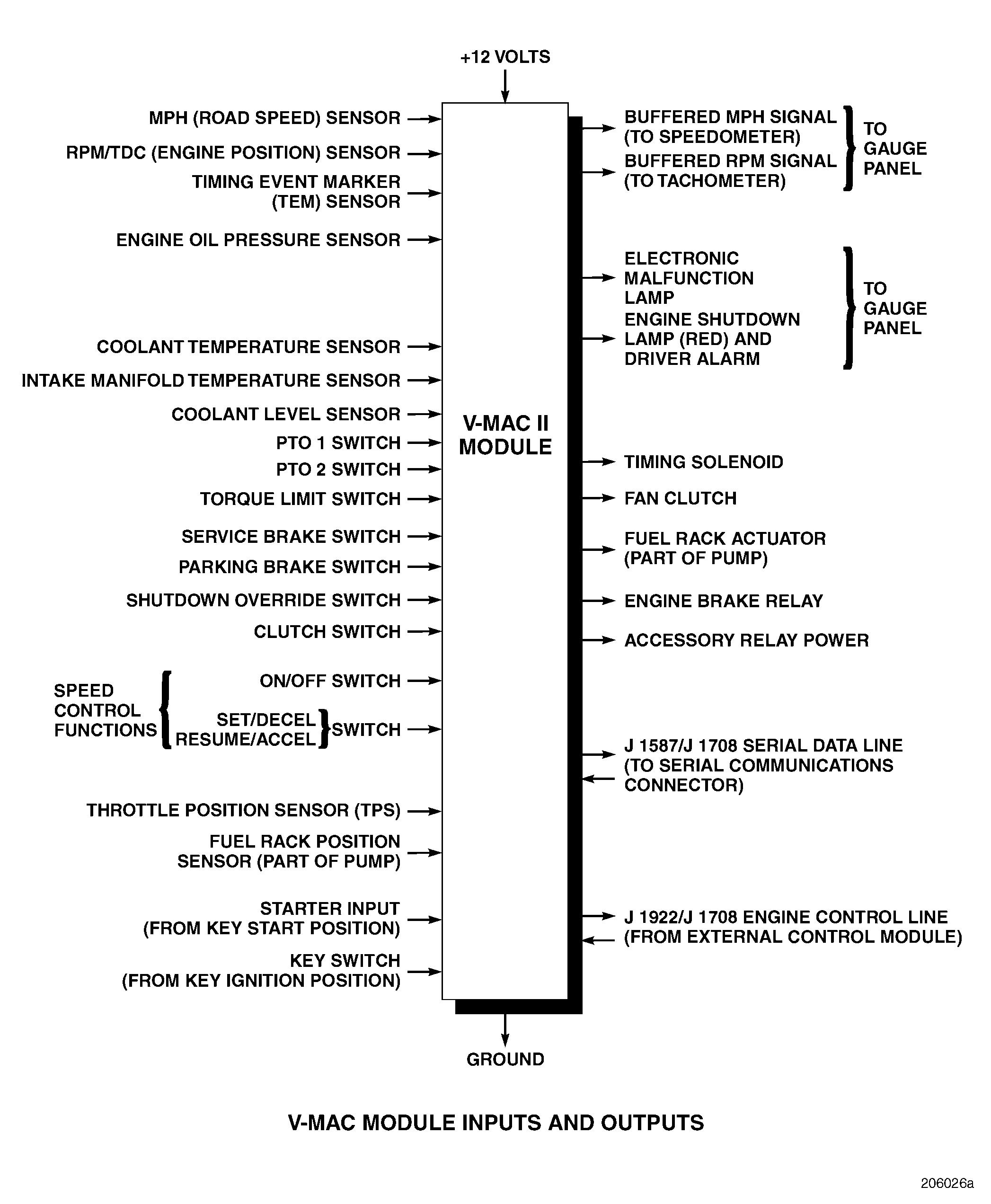
The V-MAC II (Vehicle Management and Control) system is an electronic engine control system consisting of the following components: r V-MAC II module r Fuel injection pump r Fuel rack actuator r ECONOVANCE®
To enable V-MAC II to perform the necessary engine management and control functions, the following sensors provide information to the system: r Oil pressure sensor r Intake-manifold air temperature sensor r Coolant temperature sensor r MPH sensor r RPM/TDC (engine position) sensor r Coolant level sensor r Timing Event Marker (TEM) sensor r Throttle position sensor
The following switches are used by the V-MAC II system: r Speed control ON/OFF switch r Combination SET/DECEL and RESUME/ ACCEL switch r Service brake switch r Parking brake switch r Clutch switch r PTO switches r Engine brake switch r Shutdown override switch r Torque limiting switch
To alert the driver to possible problems with the vehicle, the V-MAC II system uses the following lamps: r Electronic malfunction lamp r Shutdown lamp
Description And Operation
Component Descriptions
V-MAC II Module
The V-MAC II Module is mounted on a panel underneath the dashboard directly in front of the passenger seat.
Fuel Injection Pump
The fuel injection pump is similar to previous production pumps using mechanical governors, and is located on the right side of the engine. On this pump, the mechanical governor is replaced by an actuator assembly.
Fuel Rack Actuator
The fuel rack actuator, located on the rear of the pump, uses a proportional solenoid to provide positioning force. It works against a return spring to assure fuel shutoff if electric power is disconnected from the module. An increase in current flow moves the pump rack to a higher fuel delivery position. With a decrease in current flow, the return spring moves the rack to a lower fuel delivery position. The actuator incorporates a rack position sensor that supplies rack position information, via an electric signal, to the V-MAC II module to allow for control under all operating conditions.
The V-MAC II module is a microprocessor-based controller which provides a variety of functions including: r Rack control r Fuel injection timing advance r Variable speed control r Cruise control r Road speed limiting r Engine protection r Engine shutdown r Idle shutdown r Speedometer and tachometer outputs r Diagnostic fault logging r Engine brake control r PTO operation r ON/OFF fan control r Theft deterrence r Maintenance information
Page 3
Description And Operation
ECONOVANCE Timing Advance Mechanism
The ECONOVANCE timing advance mechanism serves as a part of the fuel injection pump drive and is located between the engine cylinder block and the injection pump. Timing is changed by rotating the injection pump camshaft relative to the engine crankshaft in response to a command from the V-MAC II module. The device has a helical spline machined into a sliding sleeve which is moved along the axis of rotation of the injection pump by engine lubricating oil. The delivery of the oil is controlled by an electrohydraulic actuator which converts the electrical output of the V-MAC II module into a proportionate rate of oil flow to the ECONOVANCE.
The electrohydraulic ECONOVANCE actuator consists of two components in a single assembly, which is mounted on the top of the ECONOVANCE mechanism. The components are:
Proportional solenoid —This type of solenoid has a core which can be moved smoothly to any position within its range of travel by varying the electric current it receives. The current is supplied and controlled by the V-MAC II module.
Hydraulic spool valve —The proportional solenoid sets the hydraulic spool valve at the position needed to control the flow of engine oil to the ECONOVANCE unit. The spool valve is not affected by the oil pressure being controlled.
System Sensors
The V-MAC II module receives information via electrical signals from the sensors described in this section.
RPM/TDC (Engine Position) Sensor
The RPM/TDC sensor is a speed sensor located in the flywheel housing. Speed sensors generate pulses of AC voltage through the principle of magnetic induction. When a conductor breaks through a magnetic field, a pulse of voltage is generated. The RPM/TDC sensor senses the passage of a series of notches machined in the forward face of the engine flywheel. These notches provide six pulses for each revolution of the engine crankshaft, spaced to occur at a fixed relationship to Top Dead Center (TDC) of each piston. The E9 flywheel uses eight notches which provide eight pulses for each engine revolution. Engine revolutions per minute (rpm) is used as the primary parameter for determining the desired timing. This sensor also provides the crankshaft position information needed for comparison with the Timing Event Marker (TEM) information to calculate the current (actual) injection timing.
MPH (Road Speed) Sensor
The miles per hour (mph) sensor is another speed sensor based on the principle of magnetic induction. It is mounted in the transmission output shaft housing, and senses the passage of a series of teeth on a tone wheel (toothed speedometer gear) mounted on the transmission output shaft. Vehicle speed is the primary parameter used for cruise control or road speed limiting modes.
Timing Event Marker (TEM)
The Timing Event Marker (TEM), located at the outside rear of the injection pump, is similar to the road speed and engine position sensors. It senses the passage of the timing finger in the injection pump rack actuator, which is adjusted to occur at port closure of the No. 1 plunger during injection pump calibration. The timing finger is also used to orient the injection pump camshaft as the pump is installed on the engine, and to set the initial injection timing.
Description And Operation
Coolant Temperature Sensor
The coolant temperature sensor is usually located in the rear of the water manifold. It monitors the temperature of the engine coolant to allow evaluation of operating conditions that cause high coolant temperatures (e.g., radiator blockage, thermostat failure, heavy load, high ambient temperatures, etc.). This sensor is also used to assist in cold start conditions.
Intake-Manifold Air Temperature Sensor
The intake-manifold air temperature sensor, located in the intake manifold, is used for accurate air/fuel ratio calculation. This information is also used for engine timing control, to prevent the formation of white smoke during engine warm-up and to prevent misfire under light load conditions.
Engine Oil Pressure Sensor
The engine oil pressure sensor, located on top of the oil filter assembly, monitors the engine oil pressure to warn of lubrication system failure.
Coolant Level Sensor
The coolant level sensor is located on the rear of the radiator near the bottom of the upper coolant tank. It monitors the level of coolant in the radiator to warn of coolant loss.
Throttle Position Sensor (TPS)
The Throttle Position Sensor (TPS), located on the side of the accelerator pedal assembly, replaces the mechanical linkage for fuel control with an electric sensor. The “drive by wire” pedal is designed to provide a system that feels similar to the standard type of pedal and mechanical linkage, but with reduced sensitivity to chassis motion for improved driver control. This sensor provides driver fuel requirement input to the V-MAC II module.
Cab And Dashboard Switches
Speed Control Switches
The speed control switches provide input from the driver to set the modes or command speeds for the speed control functions. These switches are located on the dashboard.
r Speed control ON/OFF switch r Combination SET/DECEL and RESUME/ ACCEL switch
Informational Switches
The V-MAC II system receives operating information from the following switches: r Service brake switch, located in-line within the brake system r Parking brake switch, located in-line in the parking brake circuit r Clutch switch, located under the dashboard above the clutch pedal r PTO switches, located on the dashboard r Engine brake switch, located on the dashboard
The driver activates these switches by applying the brakes, disengaging the clutch, or engaging the PTOs or engine brake.
Shutdown Override Switch
The shutdown override switch, located on the dashboard, allows a short period (30 seconds) of operation after the engine has been shut down due to a problem detected by the V-MAC II system. This enables the driver to move the vehicle, if necessary.
Torque Limiting Switch
The torque limiting switch (not available on all vehicles) is located in the transmission. It protects driveline components by reducing engine torque when it senses that the transmission is in a very low gear.
Description And Operation System Lamps
Electronic Malfunction Lamp
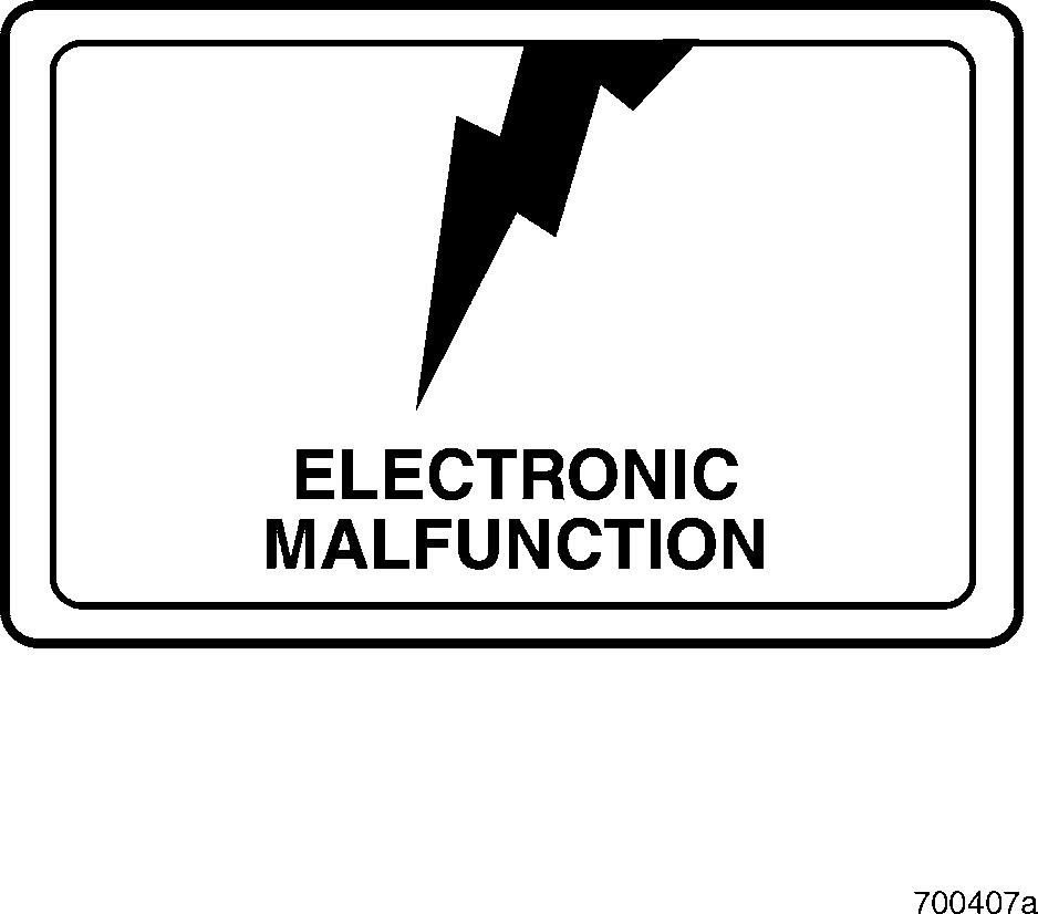
The electronic malfunction lamp also provides blink codes for system diagnostics. For an explanation of blink code activation and interpretation refer to the Blink Code Identification chart in the DIAGNOSTIC TOOLS AND PROCEDURES section.
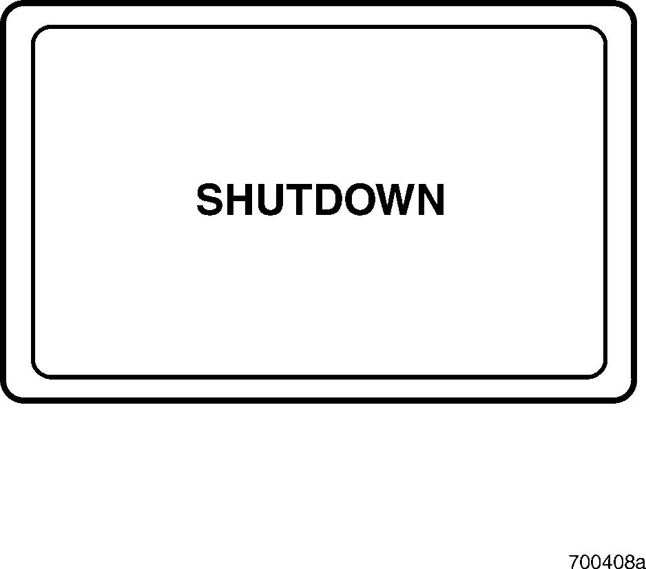
Shutdown Indicator Lamp and Alarm
The electronic malfunction lamp is located on the dashboard. It is amber in color and its function is to alert the driver to an electrical problem with the V-MAC II system.
The V-MAC II system performs a self-test each time the vehicle is started. The electronic malfunction lamp remains ON while this test is being carried out. After the self-test is completed, the lamp will turn OFF and remain OFF, unless a problem is detected.
The engine cannot be started until the two second system check is completed.
If the electronic malfunction lamp turns ON while driving the vehicle, the V-MAC II system has detected a problem.
In most circumstances the vehicle will operate when the lamp is ON, although engine performance may be affected.
The red shutdown indicator lamp, located on the dashboard, will turn ON under any of the following conditions: r Coolant level is below the minimum level r Oil pressure is below the minimum level r Engine temperature exceeds the maximum
In addition to the shutdown indicator lamp, V-MAC II also provides an audible alarm (referred to as the driver alarm). Like the electronic malfunction lamp, the shutdown lamp and driver alarm operate during the self-test and turn OFF when the test is completed. The shutdown indicator lamp and driver alarm will also turn ON when the system detects a problem which warrants shutting down the engine.
Description And Operation
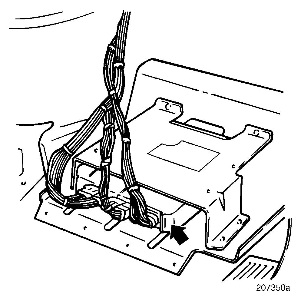
System Connectors
The V-MAC II system receives data from a variety of sensors located throughout the vehicle. Sensor connectors serve as a major component of this system by providing a connection between the sensors and the V-MAC II module. This section describes all of the connectors used in the V-MAC II system.
V-MAC II Module Connectors
There are three connectors between the main harness and the V-MAC II module. The J1A and J1B connectors are both 30-pin connectors, while the J2 connector is an 18-pin connector. Each pin on the harness connectors is marked along the outside edge of the connector. Each of the three harness connectors have 3 columns labeled 1, 2 and 3. The rows for these connectors are labeled as follows: r J1A: rows A–K r J1B: rows L–Y. r J2: rows A –F.
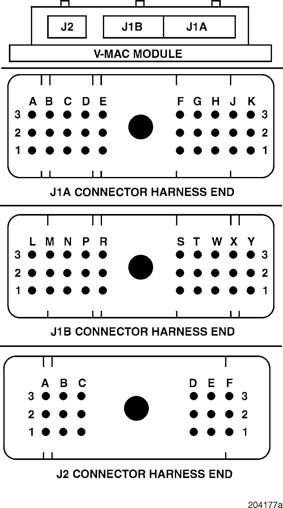
To remove any connector from the V-MAC II module, loosen the hex nut in the center of the connector and gently pull the connector from the module. For easy reference, the previous illustration shows each pin number as it appears on the harness connector. Be sure that the connector is aligned as shown below to avoid confusion when checking pin numbers.
The following is a graphic depiction of the V-MAC II module inputs and outputs.
Page 7
Description And Operation
The following tables list connector pin numbers and corresponding signal descriptions.
J1A CONNECTOR J1B CONNECTOR
Pin NumberDescription
A1 Timing solenoid PLUS (+) line
A2 Fuel rack actuator MINUS ( ) line
A3 Timing solenoid MINUS ( ) line
B1 Fuel rack actuator PLUS (+) line
B2 Fuel rack actuator PLUS (+) line
B3 Fuel rack actuator MINUS ( ) line
C1 Not used
C2 Not used
C3 Not used
D1 Not used
D2 Not used
D3 Intake manifold temperature signal (+) line
E1 Coolant temperature (+) line
E2 Coolant temperature ( ) line
E3 Intake manifold temperature signal (+) line
F1 Not used
F2 Oil pressure signal (+) line
F3 Coolant level signal (+) line
G1 Sensor power (+) line
G2 Sensor ground ( ) line
G3 MPH sensor PLUS (+) line
H1 RPM/TDC PLUS (+) line
H2 RPM/TDC MINUS ( ) line
H3 MPH sensor PLUS (+) line
J1 TEM PLUS (+) line
J2 TEM MINUS ( ) line
J3 Rack position sensor signal (+) line
K1 Rack position sensor signal (+) line
K2 Rack position sensor signal (+) line
K3 Not used
Pin NumberDescription
L1TPS signal (+) line
L2 TPS voltage reference (+) line
L3 TPS ground ( ) line
M1 Not used
M2 Not used
M3 Key switch
N1 PLUS (+) 12 volts from battery
N2 PLUS (+) 12 volts from battery
N3 PLUS (+) 12 volts from battery
P1 Chassis ground
P2 Chassis ground
P3 Engine brake relay control line
R1 Shutdown lamp and alarm signal (+) line
R2 Electronic malfunction lamp signal (+) line
R3 Accessory relay control line
S1 J 1922 data line A PLUS (+) line
S2 J 1587 serial data line A PLUS (+) line
S3 Not used
T1 J 1922 data line B MINUS ( ) line
T2 J 1587 serial data line B MINUS ( ) line
T3 Not used
W1 Not used
W2 Buffered RPM out line (speedometer signal)
W3 Buffered RPM out line (tachometer signal)
X1 Not used
X2 Not used
X3 Not used
Y1 Fan clutch control
Y2 Auxiliary No. 1 out line
Y3 Not used
Page 9
Description And Operation
J2 CONNECTOR
Pin NumberDescription
A1Not used
A2 Not used
A3 Starter signal (+) line
B1 Not used
B2 Service brake signal (+) line
B3 Parking brake signal (+) line
C1 Clutch engaged signal (+) line
C2 Speed control SET/DECEL signal (+) line
C3 Speed control ON/OFF switch signal (+) line
D1 Speed control RESUME/ACCEL signal (+) line
D2 Shutdown override signal (+) line
D3 PTO 1 selected signal (+) line
E1 PTO 2 selected signal (+) line
E2 Torque limit switch signal (+) line
E3 Not used
F1 Not used
F2 Chassis ground
F3 Not used
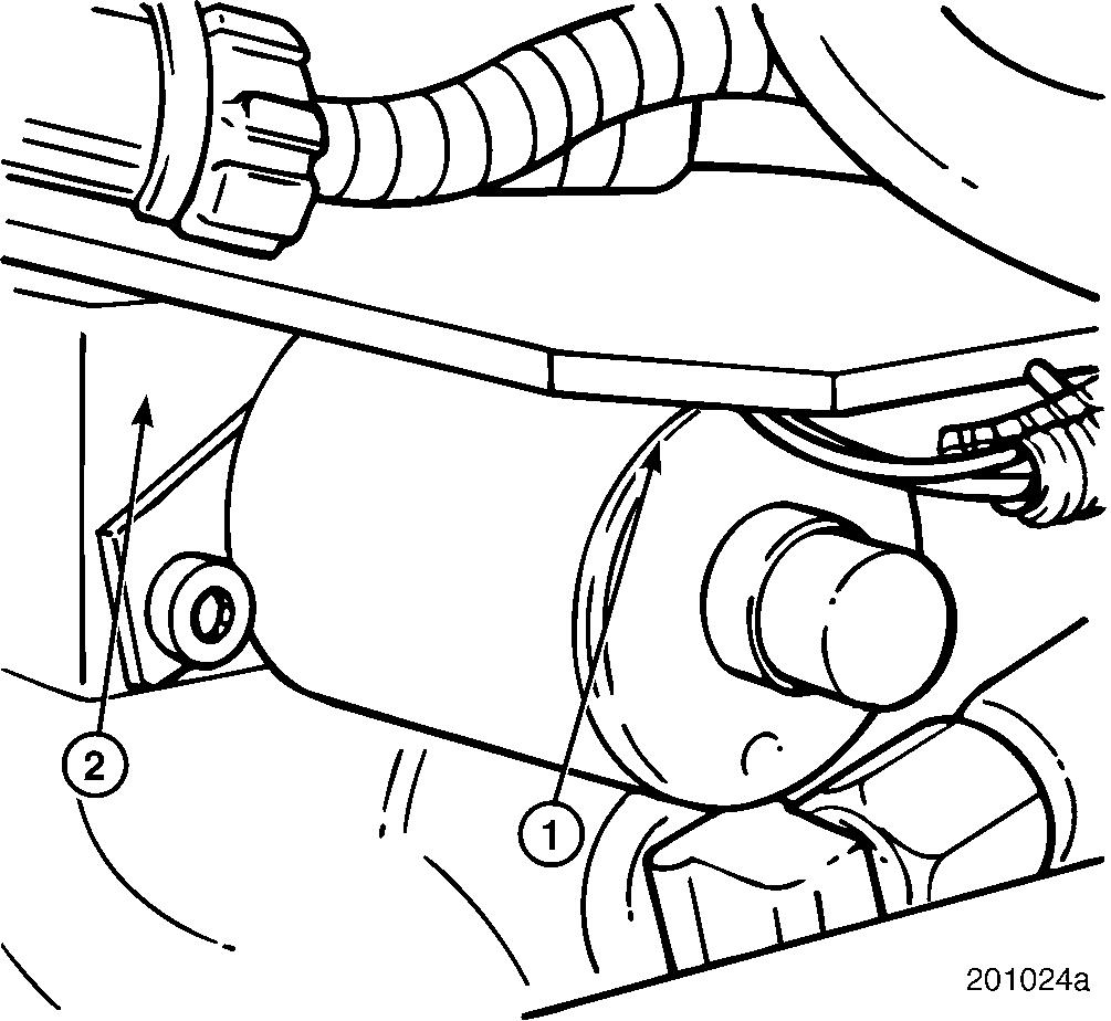
Fuel Injection Pump Connector
Figure 7 — Fuel Injection Pump Connector
On V-MAC II vehicles, the engine harness connects to the fuel injection pump via an injection pump connector harness which is integral to the pump governor housing. The harness provides easy access to the injection pump electrical pins.
The harness uses a Deutsch connector similar in appearance and function to the serial communication port connector located under the dashboard. The connector has a rotating locking collar which must be locked in place. A definite click can be felt when the collar is properly locked in place. The mating connector on the engine harness has also been changed to a Deutsch connector.
The harness is an integral part of the governor cover and cannot be removed for repairs.
Description And Operation
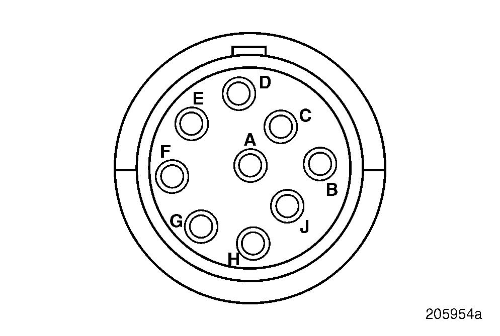
Serial Communication Port
The serial communication port is a 6-pin connector used for system diagnostics and reprogramming. It is located under the dashboard to the left of the steering column. This port is used for connecting the Pro-Link 9000® hand held-reader or the diagnostic computer. Following the illustration is a list of pin letters and designations.

31- and 23-Pin Bulkhead Connectors
Like the fuel injection pump connector, the bulkhead connectors have a rotating locking collar which must be locked in place. A definite click can be felt when the collar is properly locked in place. For a list of pin designations, refer to the appropriate electrical manual.
Bulkhead connector terminals are removed and installed in basically the same manner as the communication and pump harness connectors. Follow the instructions for terminal removal and replacement in the Connector Repair section.
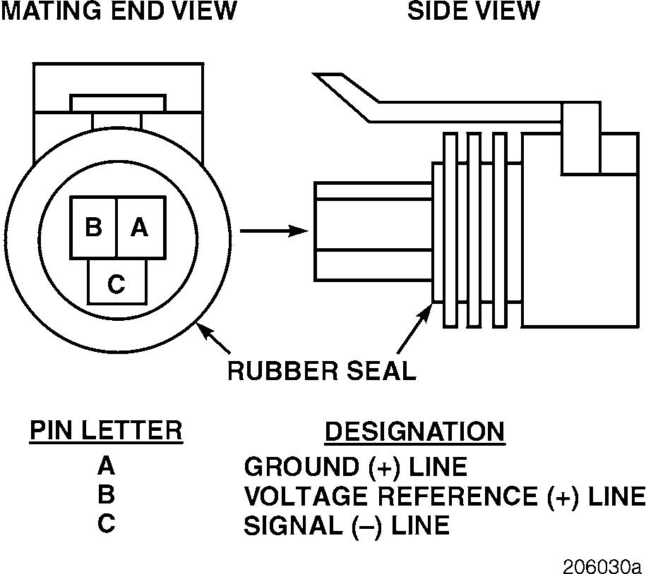
Sensor Connectors

The oil pressure sensor connector is a three-pin connector which plugs directly into the sensor. For reference, the pins are designated by letter.
Pin LetterDesignation
ASerial data link PLUS (+) line
BSerial data link MINUS ( ) line
CPLUS (+) 12 volts
DAccessory relay
E Chassis ground
F Not used
Page 11
Description And Operation
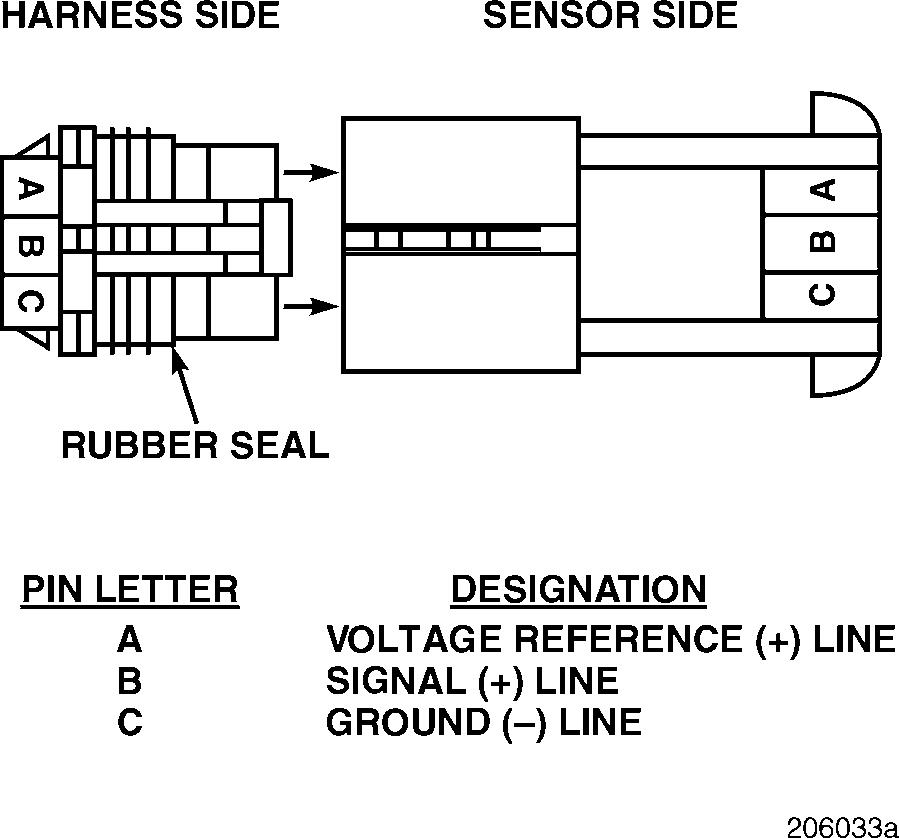
The intake-manifold air temperature sensor and the coolant temperature sensor both use a two-pin connector which plugs directly into the sensor. For reference, the pins are designated by letter.
The throttle position sensor uses a two-part, three-pin connector. The For reference, pins are designated by letter.
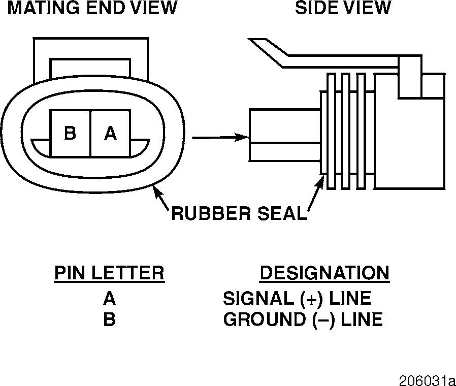
The MPH sensor, RPM/TDC sensor, timing actuator sensor, coolant level sensor and Timing Event Marker (TEM) sensor each use a two-part, two-pin connector. For reference, the pins are designated by letter.
The remaining system connectors are spade-type connectors. They are used for speed control, park and service brake, PTO and engine brake switches.
Description And Operation
Major Functions Chart
Fuel Control
r Signal line open, short to ground or short to voltage r Reference line open or grounded r r Low idle speed increases to 900 rpm. r Isochronous governor (controls to 900 rpm). r VSC and cruise control still work. r All of the above at a throttle position greater than 0%. r r r
Timing Control
r If the switch fails closed, the engine will not stop with the key.
r Cannot achieve start fuel unless RPM signal indicates starting speed, or 100% throttle position is achieved.
Description And Operation
Speed Control/Cruise Control
r r If the switch is closed, speed control will not function. r If the switch is open, speed control will not cancel. r If the switch is closed, speed control will not function. r If the switch is goes from open to closed with the parking brake OFF, VSC/SSC will not function. r If the switch is closed, speed control will not function. r If the switch is goes from open to closed, VSC/SSC will not function. r If the switches are open, cannot set SSC. r If the switches are closed, engine speed will be limited.
Road Speed Limiting
Description And Operation
Engine Protection Shutdown
Idle Shutdown
Shutdown occurs after the warm-up and shutdown times have expired, even if the engine has not yet reached the warm-up temperature.
Accessory Relay Control
If switch turns OFF or fails, the relay turns OFF 3 seconds later.
If switch signal is lost, the system will not reset after a shutdown by engaging the starter — cycle the power instead.
ON/OFF Fan Control
DIAGNOSTIC TOOLS & PROCEDURES
Diagnostic Software
The V-MAC II module contains a variety of standard integrated software packages which allow for detection, logging and retrieval of diagnostic information about the V-MAC II system.
Diagnostic software is an integral part of the system. Its purpose is to aid in troubleshooting the V-MAC II system while providing increased safety by constantly checking the hardware. The diagnostic software monitors all inputs and detects those that are out of the allowable ranges or in invalid states.
Software Functions
When an unusual condition is detected, the V-MAC II software begins a timer. If the condition does not clear within a specified period of time (known as the fault recognition period), a fault is logged. Fault recognition periods have been set according to the safety requirements of the sensor. These time periods have been specified to avoid reporting false faults, while maintaining engine and vehicle safety.
After a failure is detected, the diagnostic software will perform the following functions:
1.The electronic malfunction lamp, located on the dashboard, will go ON. This lamp will remain ON for active faults, and go OFF when there are no longer any active faults present in the system.
2.A fault message will be sent in a standard format on the SAE/ATA serial line to alert other devices of this failure. A similar message will be transmitted when the failure is cleared.
3.The data normally transmitted on the SAE/ATA serial line for this sensor will be replaced with a “Bad Data” indicator. This will signal the other devices on the serial line to ignore the data for this sensor.
In the event of a circuit failure, a default value will be reported. This default value will allow the engine or vehicle to operate even though the V-MAC II module does not have any information from the failed circuit.
4.The V-MAC II module will update the fault table in its internal memory. The fault table contains a record of how many times the failure has occurred. The occurrence count is limited to 15, and the stored codes will remain in memory until cleared by a diagnostic computer, or until the information is no longer useful for diagnostic purposes.
All of the faults logged by the V-MAC II system are recoverable. This means that if the unusual condition returns to normal for a continuous period of time, the fault will be cleared and the fault lamp will go OFF. However, the occurrence will be logged in the fault table to aid in future troubleshooting.
SAE/ATA Serial Line
The V-MAC II diagnostic software is closely tied to the SAE/ATA serial line. This provides an easy means of troubleshooting the system, since a complete fault history can be retrieved from the SAE/ATA serial line with a diagnostic tool such as the Pro-Link 9000 or a diagnostic PC.
When a problem occurs in the SAE/ATA J 1708 serial line, the Pro-Link 9000 and the diagnostic PC may not be able to read the information from the vehicle. The fault lamp will be ON, and the dash switches will have to be used to read the blink codes. The Pro-Link will display the message “No Data Received.”
For SAE/ATA standard terminology, refer to the SAE Message Descriptions section.


