
3 minute read
DIAGNOSTIC TOOLS & PROCEDURES


IBM-Compatible PC
J 1708 Serial Data Link Adaptor
The personal computer communicates with the vehicle via the J 1708 serial data link adaptor. The Pro-Link or the J 38351 (B) serial link adaptor can be used as an interface in place of this adaptor.
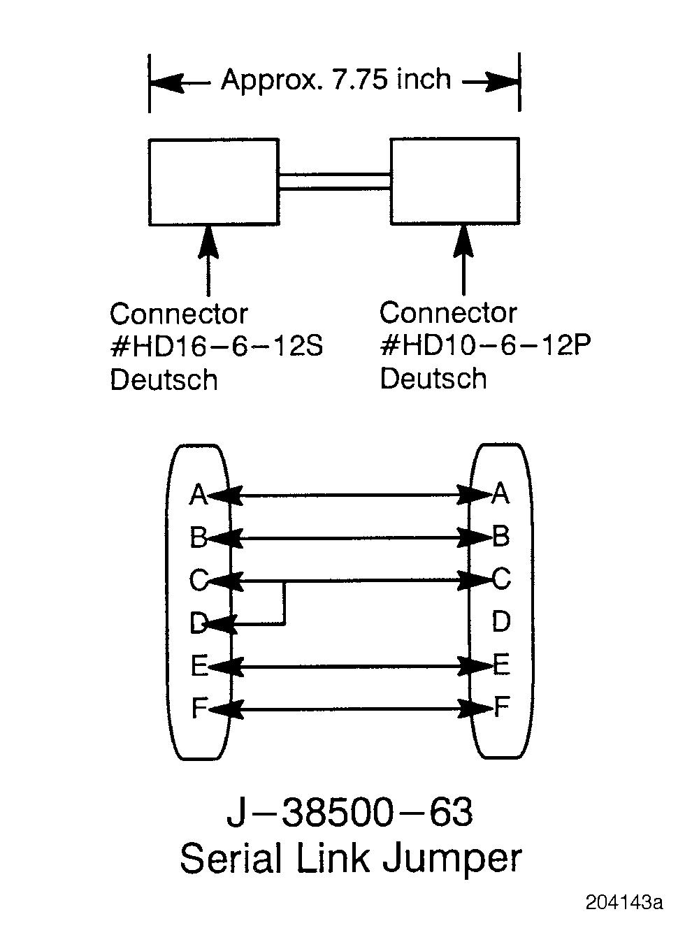
J 38500-63 Serial Link Jumper
The Personal Computer (PC) is the most advanced diagnostic tool available for troubleshooting the V-MAC II system. In addition to performing all the functions of the Pro-Link 9000, it allows enhanced system diagnostics.
The personal computer also permits information specific to the vehicle to be entered and stored in the V-MAC II module’s internal memory, and provides more flexibility in password selection. Any 100% IBM-compatible computer will work with the system. In order to connect a computer to the vehicle, a serial link interface is required. The ATA serial link adapter (part No. J 38351 or J 38351-B) or the Pro-Link 9000 can be used as the interface device.
In addition, the V-MAC II SERVICE DIAGNOSTICS software package MUST BE loaded. This software package, as well as complete instructions for installing and running the program, is available through your MACK distributor. Be sure to follow the instructions completely.
The J 38500-63 serial link jumper should be used with both the J 1708 Serial data link adaptor and the Pro-Link. The jumper provides the ability to turn the V-MAC II system ON without having to turn on the key. This is not only convenient for programming, but is also very important for diagnostic troubleshooting.
Page 21
DIAGNOSTIC TOOLS & PROCEDURES
If you do not have a jumper and the diagnostic procedure requires that you Connect the serial link jumper into the serial communication port, there are two alternative solutions: r Serial Communication Port — Connect a wire from pin C of the serial communication port to pin D of the port. r Accessory Relay Jumper — Disconnect the white 16-gauge wire on the accessory relay post B, which leads to the V-MAC II module. Then connect a jumper wire from the electrical equipment panel post, marked BATTERY, to the accessory relay post B. The accessory relay should pull in.
Diagnostic Blink Codes
Determining Diagnostic Blink Codes
The V-MAC II module is capable of blinking a twodigit blink code for each of the active faults in the V-MAC II system. These codes are displayed on the electronic malfunction lamp, located on the dashboard. The diagnostic blink code allows the technician to diagnose an active fault in the system without using an expensive diagnostic tool such as the Pro-Link 9000 or PC. Diagnostic blink codes can be used for isolating and troubleshooting any active faults in the V-MAC II system.
To properly activate and use the blink codes, follow the steps below.
1.Turn the ignition key to the ON position and wait while the system performs its twosecond self test.
2.If the electronic malfunction lamp remains ON after the self test is completed, there is an active fault.
3.With the speed control ON/OFF switch in the OFF position, press and hold the SET/ DECEL or the RESUME/ACCEL switch until the fault lamp goes OFF.
4.The fault lamp will remain OFF for approximately 1 second. The period of time during which the fault lamp is OFF will be referred to as an idle time.
5.Immediately after the idle time, the V-MAC II module will begin to flash a two-digit blink code. The two digits of the code will be separated by a one-second idle time.
6.Each digit of the blink code may consist of up to eight flashes. Both the ON and OFF time for each flash will be one-fourth of a second.
7.Count the ON flashes of the fault lamp in order to determine the two-digit blink code.
8.When there are multiple active faults present in the system, display of each fault must be requested separately, since only one active fault can be blinked per request. To request that another fault be displayed, hold in the SET/DECEL or RESUME/ACCEL switch until the fault lamp goes OFF. The blink code sequence for the next fault will begin after the one-second idle time.
Remember that there will be a one-second idle time between the two digits of the code.
If the request for display of a fault is repeated while V-MAC is already blinking an active fault, the current blink code sequence will stop and the blink code sequence for the next active fault will be displayed.
If an active fault is cleared while V-MAC is blinking that fault, the procedure will not stop.
After every complete blinking sequence, the fault lamp will return to normal functions. It will remain ON for active faults and OFF for inactive faults.


