4 minute read
DIAGNOSTIC CODE 7-1


Checking for a short to ground
Test 200
Checking for a short to ground in the switch
1.With the ignition key in the OFF position, check for continuity from either pin on the service brake switch to a good ground. Engage and disengage the service brake.
If at any time there is continuity between the switch and ground, replace the service brake switch. Retest to be sure the problem has been corrected.
1.Disconnect the J1A and J1B V-MAC II module connectors
V-MAC II module.
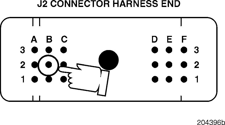
2.Check for continuity from J2 connector pin B2 (the service brake signal [+] line) to a good ground.
3.Check for continuity between J2 connector pin B2 (the service brake signal [+] line) and each of the other pins (one at a time) on the J1A, J1B and J2 connectors.
If there is continuity with another pin or to ground, locate and repair the short in the harness. Retest to be sure the problem has been corrected.
If there is no continuity, proceed to Test 200.
If there is no continuity with ground, there is a break in the wire which supplies the service brake signal to J2 connector pin B2. Repair or replace the wire. Retest to be sure the problem has been corrected.
DIAGNOSTIC CODE 7-5
DIAGNOSTIC BLINK CODE 7-5
When performing electrical tests, it is important to wiggle wires and connectors to identify intermittent connection problems.
Test 1
Checking for an open in the sensor in the pump
7-5
5.Visually inspect the pins and crimps in the injection pump connector, at the pump end of the harness, for the cause of the open.
If there is a repairable condition, repair. Retest to be sure the problem has been corrected.
If there is not a repairable condition, send the pump to a certified pump shop for repair of the pump or integral jumper harness. Retest to be sure the problem has been corrected.
Test 2
Checking for an open in the sensor in the pump
1.Turn the ignition key to the OFF position.
2.Disconnect the engine harness from the injection pump connector.
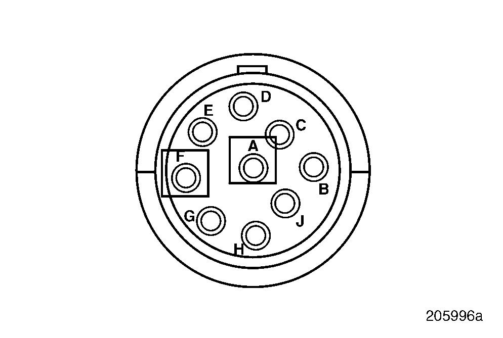
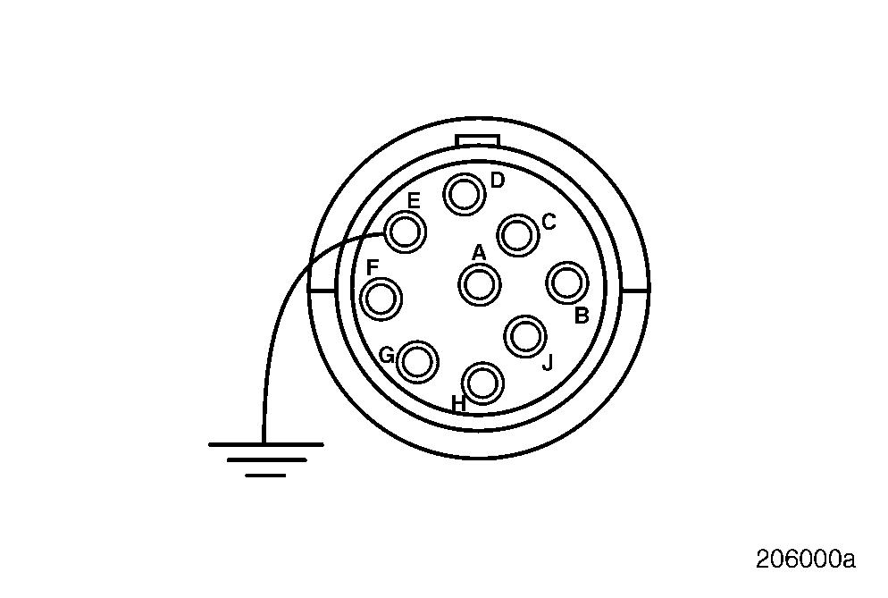
3.Measure the resistance between Deutsch pins F and E.
4.Measure the resistance between Deutsch pins A and F.
If the resistance for both checks is between 15 and 25 ohms, proceed to Test 2.
If the resistance is not between 15 and 25 ohms, continue with the next step.
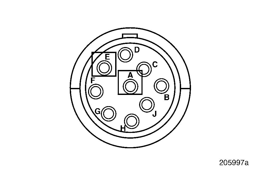
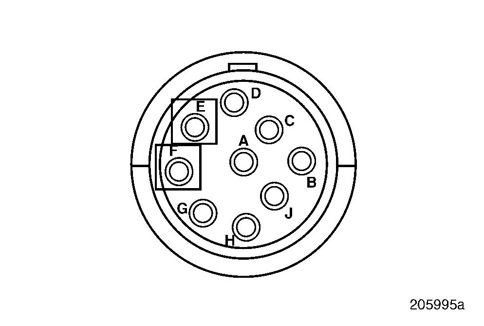
1.Measure the resistance between Deutsch pins A and E.
If the resistance is between 30 and 50 ohms, proceed to Test 4.
If the resistance is not between 30 and 50 ohms, continue with the next step.
2.Visually inspect the pins in the Deutsch connector (engine harness end) of the integral jumper harness for the cause of the open.
If there is a repairable condition, repair. Retest to be sure the problem has been corrected.
If there is not a repairable condition, send the pump to a certified pump shop for repair to the pump or integral jumper harness. Then retest to be sure the problem has been corrected.
Test 4
DIAGNOSTIC CODE 7-5
Checking for an open in the harness
DIAGNOSTIC CODE 7-5
1.Disconnect the J1A and J1B connectors from the V-MAC II module.
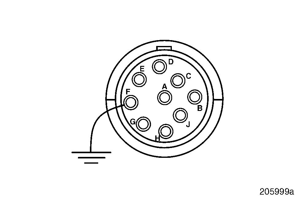
2.Connect a jumper, on the pump end of the engine harness, from Deutsch pin A to a good ground.
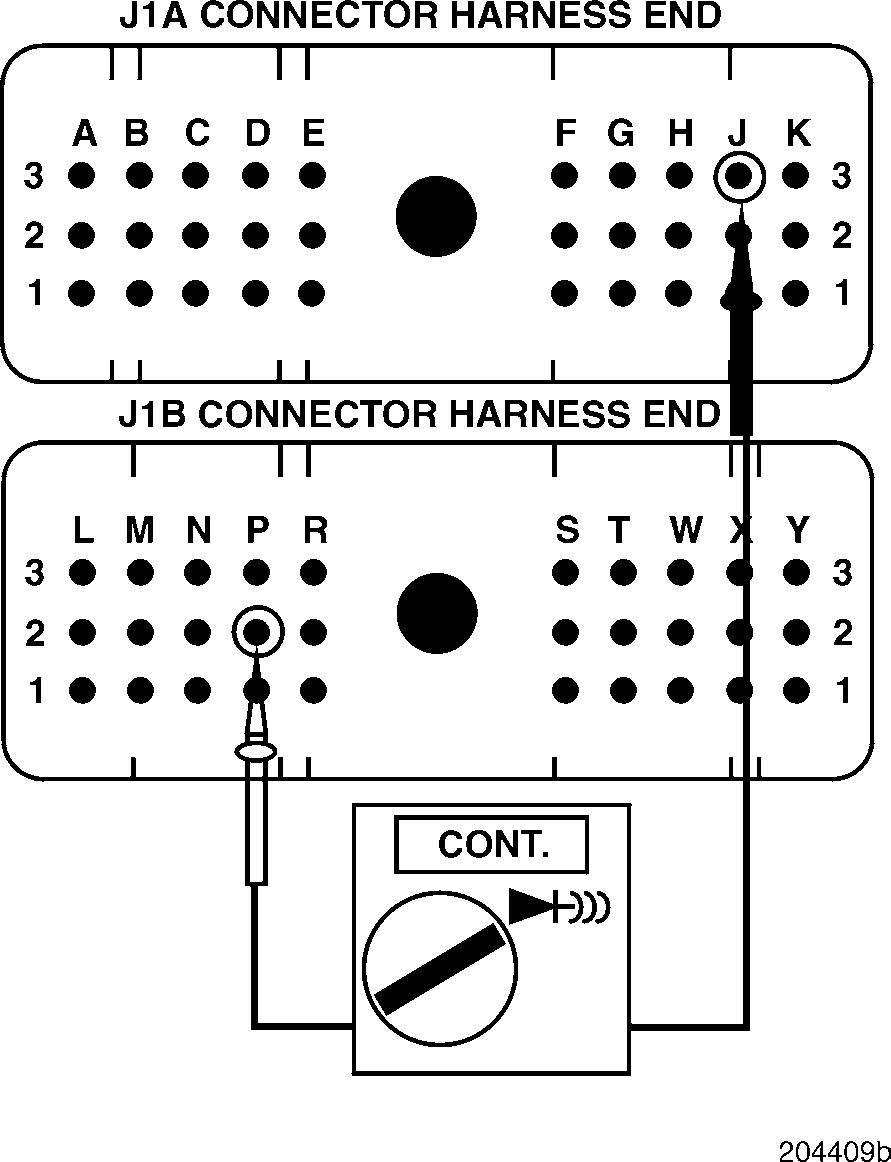
3.Check for continuity between J1A connector pin J3 (the rack position sensor signal [+] line) and J1B connector pin P2 (chassis ground).
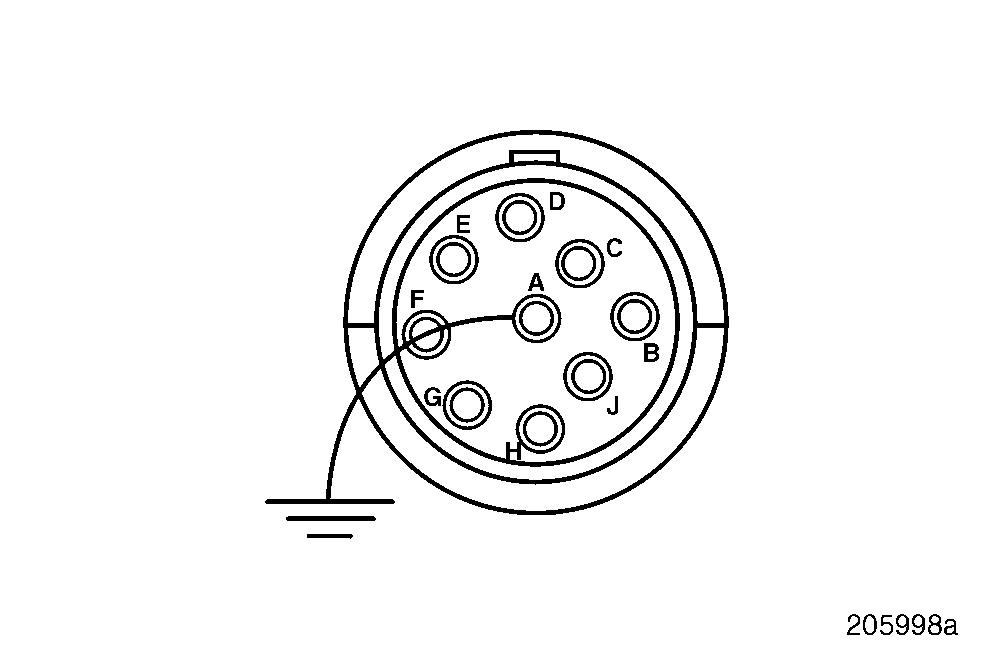
4.Connect a jumper, on the pump end of the engine harness, from Deutsch pin F to a good ground.
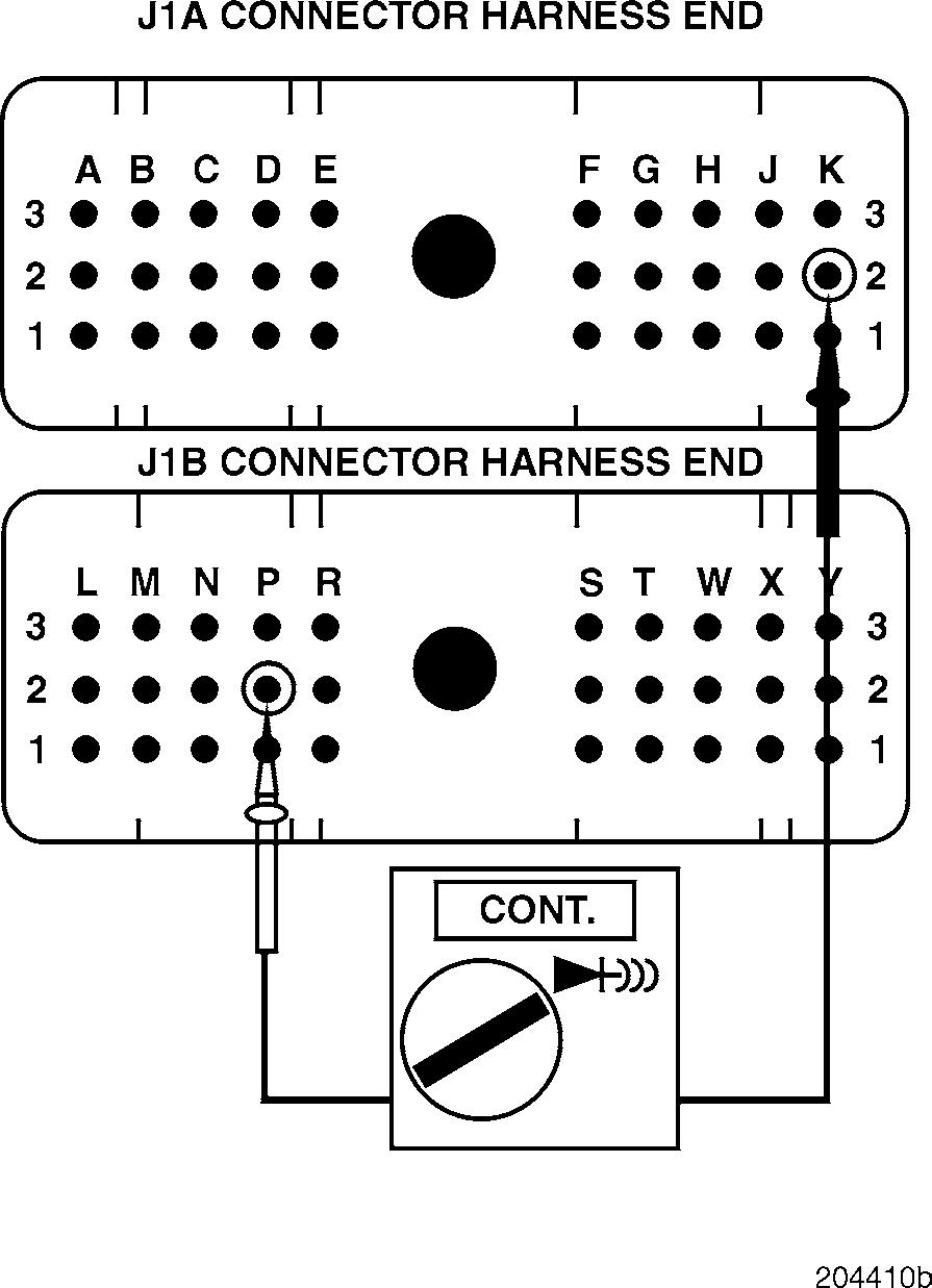
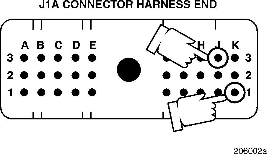
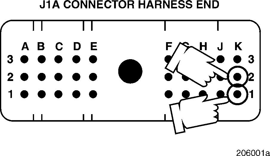
5.Check for continuity between J1A connector pin K2 (the rack position sensor signal [+] line) and J1B connector pin P2 (chassis ground).
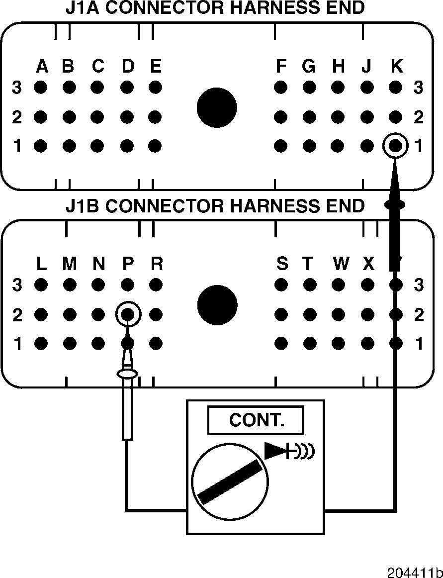
6.Connect a jumper, on the pump end of the engine harness, from Deutsch pin E to a good ground.
7.Check for continuity between J1A connector pin K1 (the rack position sensor signal [+] line) and J1B connector pin P2 (chassis ground).
If there is continuity on each pair tested, proceed to Test 8.
If there is no continuity, there is an open in the harness on the pair which did not show continuity. Locate and repair the open. Retest to be sure the problem has been corrected.
Test 8
DIAGNOSTIC CODE 7-5
Checking for an open in the pump connector
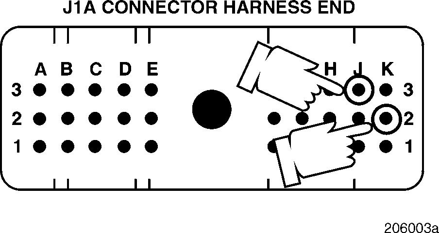
4.Measure the resistance between J1A connector pins K1 (the rack position sensor signal [+] line) and J3 (the rack position sensor signal [+] line).
5.Measure the resistance between J1A connector pins K2 (the rack position sensor signal [+] line) and J3 (the rack position sensor signal [+] line).
If the resistance is greater than 60 ohms in any pair, verify that there is no cause for this resistance at the bulkhead connector.
If the resistance is less than 60 ohms in each pair, proceed to Test 16.
If no cause is found, there is an open on the pair which showed high resistance (at the injection pump connector or on the injection pump end of the integral jumper harness). Locate and repair the open if possible.
The logical place for high resistance is in the engine harness end connector. Remove the wire in question and check for correct wire crimp. If no problem is found, look for a poor electrical contact between mating terminals.
Test 16
Checking for a defective V-MAC II module, or an open or loose connector
1.With the ignition key in the OFF position, reconnect the V-MAC II connectors.
2.Turn the ignition key to the ON position.
If code 7-5 is still active, check the V-MAC II module and connector for dirt, loose or broken pins, or repairable damage. If no repairable conditions are evident, replace the V-MAC II module. Retest to be sure the problem has been corrected.
2.Reconnect
3.Measure
If code 7-5 is not active, there was an open at the injection pump connector, or on the injection pump end of the integral jumper harness. Inspect all connectors to ensure proper connections.
DIAGNOSTIC CODE 7-6
DIAGNOSTIC BLINK CODE 7-6
When performing electrical tests, it is important to wiggle wires and connectors to identify intermittent connection problems.
Test 1
DIAGNOSTIC CODE 7-6
Checking for a short in the sensor in the pump
Test 2
Checking for a short in the sensor in the pump
1.Turn the ignition key to the OFF position.
2.Disconnect the engine harness from the injection pump connector.
3.Measure the resistance between Deutsch pins F and E.
4.Measure the resistance between Deutsch pins A and F.
If the resistance for both checks is between 15 and 25 ohms, proceed to Test 2.
If the resistance is not between 15 and 25 ohms, send the pump to a certified pump shop for repair. Retest to be sure the problem has been corrected.
1.Measure the resistance between Deutsch pins A and E.
If the resistance is between 30 and 50 ohms, proceed to Test 4.
If the resistance is not between 30 and 50 ohms, send the pump to a certified pump shop for repair. Retest to be sure the problem has been corrected.


