3 minute read
DIAGNOSTIC CODE 5-1


Checking for an open in the V-MAC II module
Test 64
Checking for bad contact in the sensor connector
1.Reconnect the TPS.
2.Start the engine and flex the harness near the sensor.
If at any time the fault becomes inactive, repair or replace the sensor connector. Retest to be sure the problem has been corrected. Otherwise, replace the throttle position sensor. Retest to be sure the problem has been corrected.
1.Connect
2.Turn the ignition key to the ON position.
If the active fault changes from voltage low (code 5-1) to voltage high (code 5-2), proceed to Test 64.
If the active fault does not change, turn the ignition key to the OFF position. Check the V-MAC II module J1B connector for loose pins which could cause an open at the signal. Repair the open or replace the V-MAC II module. Retest to be sure the problem has been corrected.
DIAGNOSTIC CODE 5-2
DIAGNOSTIC BLINK CODE 5-2
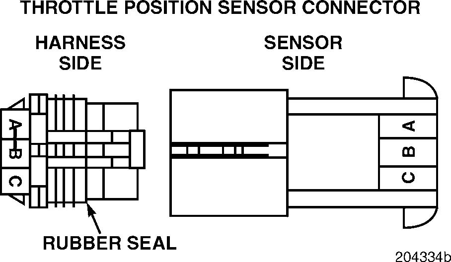
THROTTLE POSITION SENSOR (TPS) TESTS
When performing electrical tests, it is important to wiggle wires and connectors to identify intermittent connection problems.
Blink Code 5-2
PID 91
SID
FMI 3
MID 142
Name Throttle Position Sensor (TPS)
Failure Voltage above normal or shorted high
Test 1
Checking for a change in the blink code with sensor removed
1.Turn the ignition key to the OFF position.
2.Disconnect the TPS.
3.Turn the ignition key to the ON position.
If code 5-2 has changed to code 5-1, proceed to Test 2.
If the code has not changed, proceed to Test 3.
Test 2
DIAGNOSTIC CODE 5-2
Checking the voltage on the pedal PLUS (+) line
1.Turn the ignition key to the OFF position.
2.Disconnect the J1B connector from the V-MAC II module.
3.Connect the serial link jumper into the serial communication port.
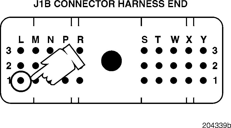
4.Measure the voltage from J1B connector pin L1 (the TPS signal [+] line) to a good ground.
If the voltage is greater than 0.5 volts, the signal line is shorted to voltage in the harness or connector. Retest to be sure the problem has been corrected.
If there is no voltage, proceed to Test 6.
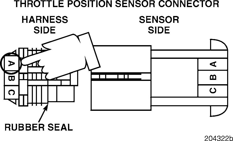
1.Measure the voltage from harness connector pin A (the voltage reference [+] line) to a good ground.
If the voltage is greater than 5.25 volts, proceed to Test 5.
If the voltage is less than 5.25 volts, proceed to Test 4.
Test 3
Checking for the signal line shorted to voltage in the harness
Test 4
Checking for voltage on the ground line
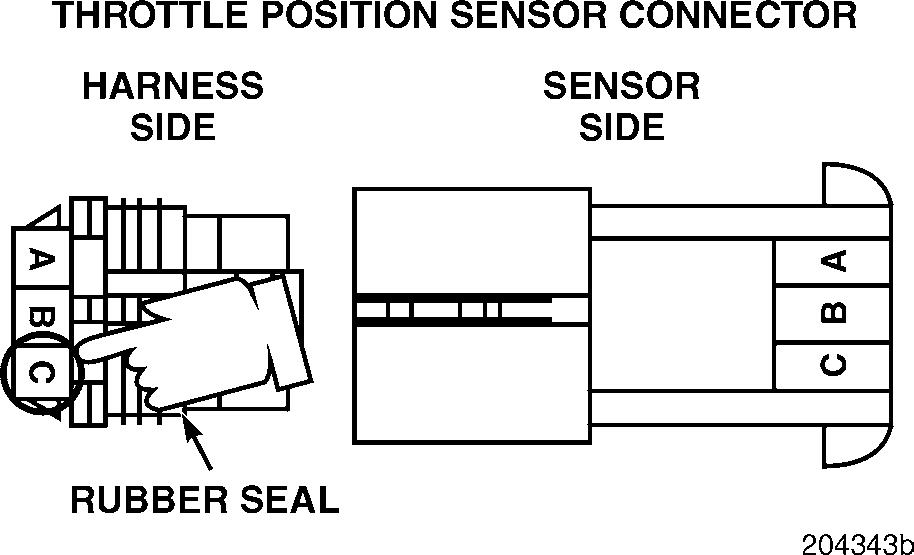
1.Measure the voltage from harness connector pin C (the ground [ ] line) to a good ground.
If the voltage is greater than 0.5 volts, proceed to Test 9.
If there is no voltage, proceed to Test 8.
Test 5
DIAGNOSTIC CODE 5-2
Checking for a short to voltage on the pedal PLUS (+) line
Test 6
Checking for a pin-to-pin short on the signal line
1.Turn the ignition key to the OFF position.
2.Disconnect the J1B connector from the V-MAC II module.
3.Connect the serial link jumper into the serial communication port.
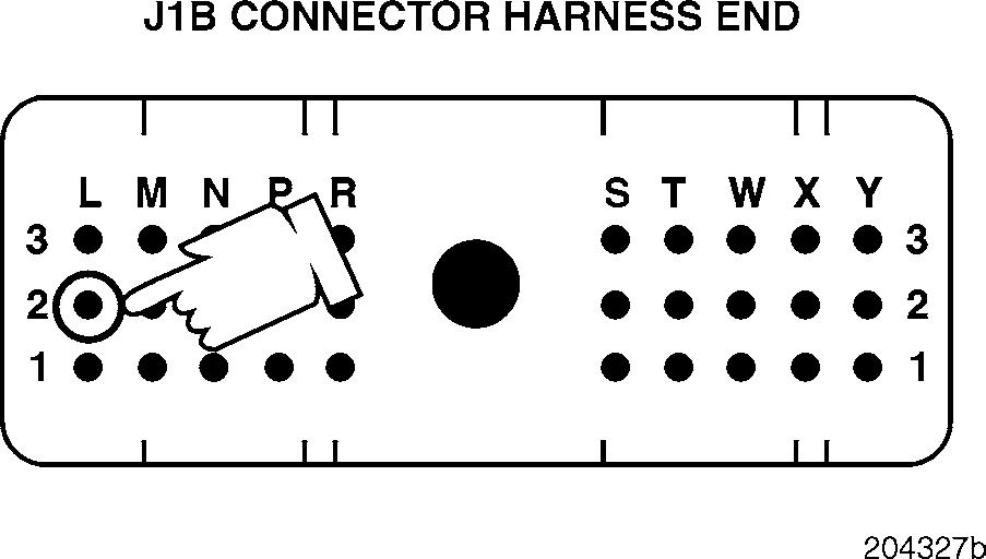
4.Measure the voltage from J1B connector pin L2 (the TPS voltage reference [+] line) to a good ground.
If the voltage is greater than 0.5 volts, the pedal PLUS [+] line is shorted to more than 5.25 volts in the harness or at a connector. Retest to be sure the problem has been corrected.
If there is no voltage, proceed to Test 10.
1.Disconnect the serial link jumper.
2.Disconnect the J1A and J2 connectors from the V-MAC II module.
3.Check for continuity between J1B connector pin L1 (the TPS signal [+] line) and each of the other pins (one at a time) on the J1A, J1B and J2 connectors.
If there is continuity with another pin, the signal line is shorted to more than 5.25 volts in the harness or at a connector. Locate and repair the short. Retest to be sure the problem has been corrected.
If there is no continuity, replace the V-MAC II module. Retest to be sure the problem has been corrected.
Test 8
Checking for an open in the ground line
If the voltage is greater than 0.5 volts, the ground line is shorted to more than 5.25 volts in the harness or in the connectors. Locate and repair the short and replace the V-MAC II module. Retest to be sure the problem has been corrected.
If there is no voltage, proceed to Test 18.
Test 10
Checking for a pin-to-pin short in the harness or V-MAC II module
1.Turn
2.Check for continuity from
If there is continuity, proceed to Test 16.
If there is no continuity, proceed to Test 17.
Test 9
Checking for a short to voltage in the harness
1.Disconnect the serial link jumper.
2.Disconnect the J1A and J2 connectors from the V-MAC II module.
3.Check for continuity between J1B connector pin L2 (the TPS voltage reference [+] line) and each of the other pins (one at a time) on the J1A, J1B and J2 connectors.
If there is continuity with another pin, the TPS voltage reference [+] line is shorted in the harness or in the connectors. Retest to be sure the problem has been corrected.
1.Turn the ignition key to the OFF position.
2.Disconnect the J1B connector from the
3.Connect the serial link jumper into the serial communication port.
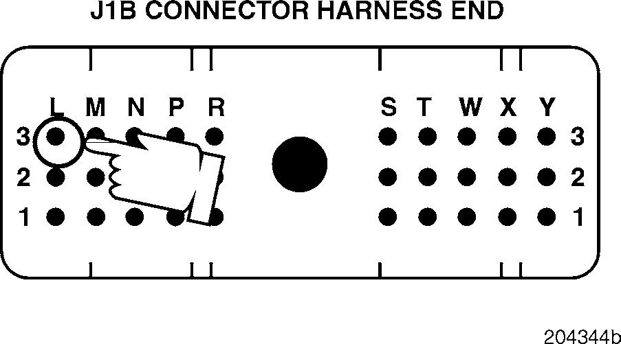
4.Measure the voltage from J1B connector pin L3 (the TPS ground [ ] line) to a good ground.
If there is no continuity, replace the V-MAC II module. Retest to be sure the problem has been corrected.


