2 minute read
DIAGNOSTIC CODE 5-9


OR 5-10
Test 40
Checking the V-MAC II module
1.Disconnect the serial link jumper.
2.Reconnect the J1B connector.
3.Turn the ignition key to the ON position.
If code 5-9 becomes active, check the V-MAC II module for dirt. loose or broken pins or repairable damage. If no repairable conditions are evident, replace the V-MAC II module. Retest to be sure the problem has been corrected.
If code 5-9 is not active, the procedures have corrected the problem. Check all connectors to ensure proper connections.
DIAGNOSTIC CODE 6-5
DIAGNOSTIC BLINK CODE 6-5
Battery Voltage Tests
When performing electrical tests, it is important to wiggle wires and connectors to identify intermittent connection problems.
Test 1
Checking the system voltage with the engine not running
1.With the engine not running, measure the voltage from the BATT stud on the electrical equipment panel to a good ground.
If the voltage is greater than 10.5 volts, proceed to Test 2.
If the voltage is less than 10.5 volts, locate and repair the cause for the low battery voltage. Retest to be sure the problem has been corrected.
Test 2
Checking the system voltage with the engine running
1.Start the engine and let it idle.
2.Measure the voltage from the BATT stud on the electrical equipment panel to a good ground.
If the voltage is between 11.5 volts and 16.0 volts, proceed to Test 4.
If the voltage is not within the specified range, check the charging system for a malfunction.
Test 4
DIAGNOSTIC CODE 6-5
Checking for voltage at the V-MAC II module
If battery voltage is present, proceed to Test 8.
If the voltage measured differs significantly from the voltage measured in Test 1, proceed to Test 9.
Test 8
Checking for an open ground circuit
1.Turn the ignition key to the OFF position.
2.Disconnect
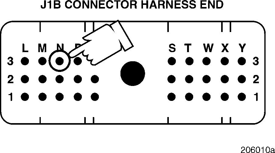
3.Measure the voltage from J1B connector
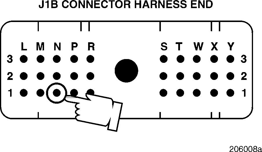
N1, N2 and N3 (one at a time) to a good ground.
1.Turn the ignition key to the OFF position.
2.Disconnect the J1B from
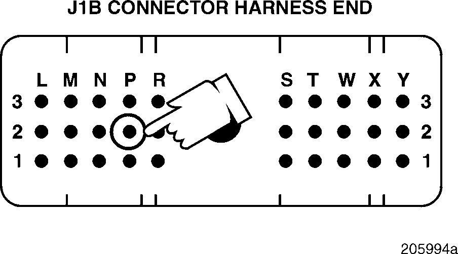
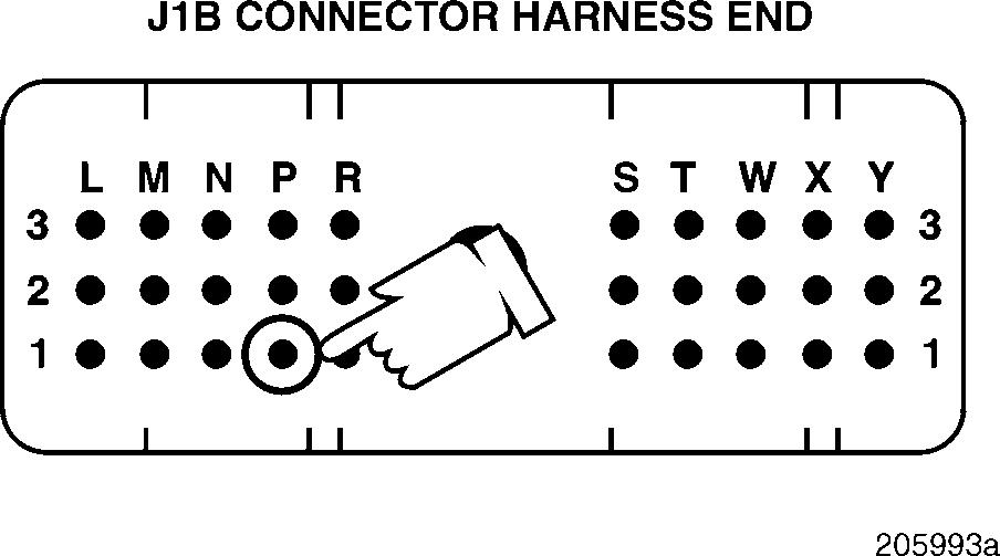
3.Check for continuity from J1B connector pins P1 and P2 (one at a time) to a good ground.
If there is continuity on both pins, proceed to Test 16.
If there is a pin without continuity, check the suspect circuit for an open. Retest to be sure the problem has been corrected.
Test 9
Checking for a pin-to-pin short
1.Turn the ignition key to the OFF position and remove fuse CB-20.
2.Disconnect the J1A, J1B and J2 connectors from the V-MAC II module.
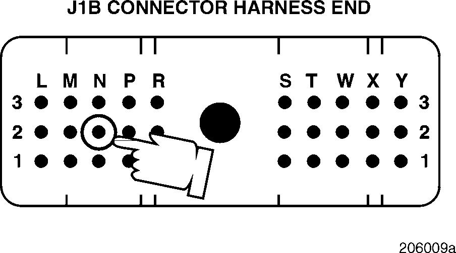
3.Check for continuity between J1B connectors pins N1, N2 and N3 (one at a time) and each of the other pins (one at a time) on the J1A, J1B and J2 connectors.
If there is a pin with continuity, locate and repair the short. Retest to be sure the problem has been corrected.
If there is no continuity, proceed to Test 18.
Test 16
Checking for loose pins or a defective V-MAC II module
1.Turn the ignition key to the OFF position.
2.Disconnect the J1B connector from the V-MAC II module.
3.Visually inspect J1B connector pins N1, N2, N3, P1 and P2 for dirt, loose pins or deformed contacts.
4.Find the gray J 35616-2 male test lead from the J 38581 V-MAC jumper wire kit. Align the male test lead with J1B connector pin N1 and gently push the test lead into the connector pin. Repeat this process for J1B connector pins N2, N3, P1 and P2 (one at a time).
If there is a repairable open or terminals feel loose, repair or replace the J1B connector. Retest to be sure the problem has been corrected.
If the test lead is making good contact with the J1B connector pins, proceed to Test 32.


