1 minute read
DIAGNOSTIC CODE 1-7


Checking for pin-to-pin continuity
Test 16
Checking for pin-to-pin continuity
1.Turn the ignition key to the OFF position.
2.Remove the jumper from pin A to ground.
3.Disconnect the J2 connector from the V-MAC II module.
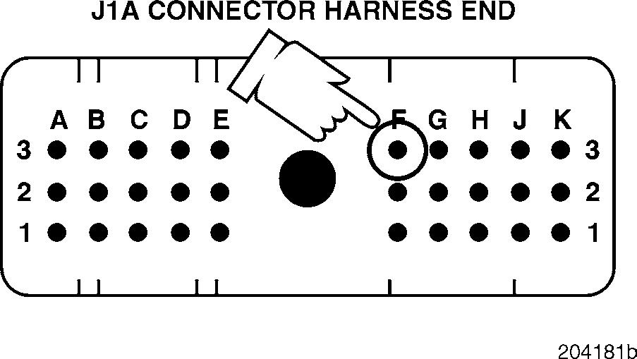
4.Check for continuity between J1A connector pin F3 (the coolant level signal [+] line) and each of the other pins (one at a time) on the J1A, J1B and J2 connectors.
If there is continuity with another pin, locate and repair the short. Retest to be sure the problem has been corrected.
If there is no continuity, proceed to Test 20.
1.Disconnect the J2 connector from the V-MAC II module.
2.Disconnect the jumper between pins A and B.
3.Check for continuity between J1A connector pin F3 (the coolant level signal [+] line) and each of the other pins (one at a time) on the J1A, J1B and J2 connectors.
If there is continuity with another pin, locate and repair the short. Retest to be sure the problem has been corrected.
If there is no continuity, proceed to Test 32.
Test 20
Checking for a defective V-MAC II module
1.Reconnect the sensor.
2.Reconnect the V-MAC II harness connectors.
3.Turn the ignition key to the ON position.
If code 1-7 is still active, replace the V-MAC II module. Retest to be sure the problem has been corrected.
If code 1-7 is no longer active, the procedure has corrected the problem. Clean and inspect the connections.


