2 minute read
REPAIR AND ADJUSTMENT PROCEDURES


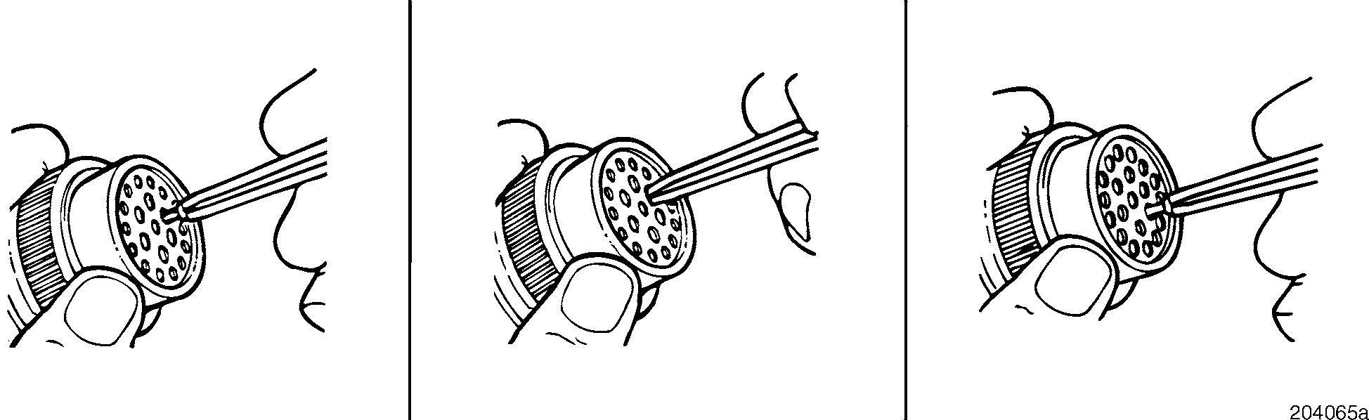
CONTACT REMOVAL
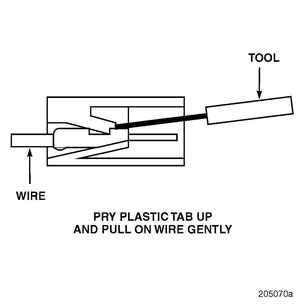
1.With the rear insert toward you, snap the appropriate-size extractor tool over the wire of the contact to be removed.
2.Slide the tool along the wire into the insert cavity until it engages the contact and resistance is felt.
Do not twist or insert the tool at an angle.
3.Pull the contact-wire assembly out of the connector.
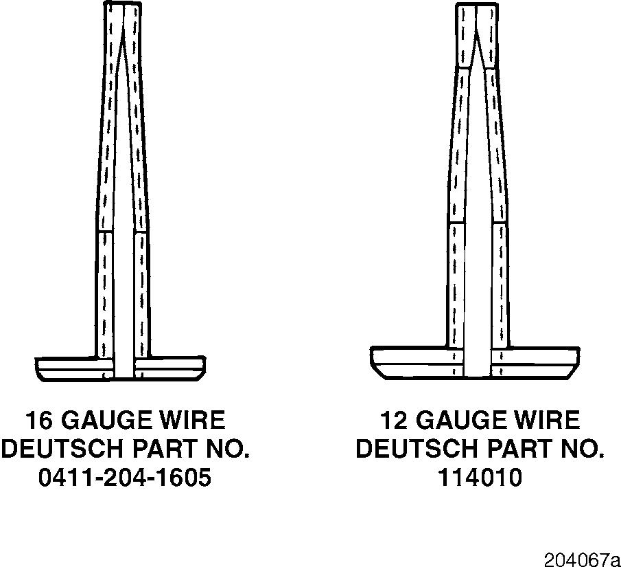
Contact Replacement
Use only the appropriate size Deutsch plastic tool. DO NOT use any other kind of tool.
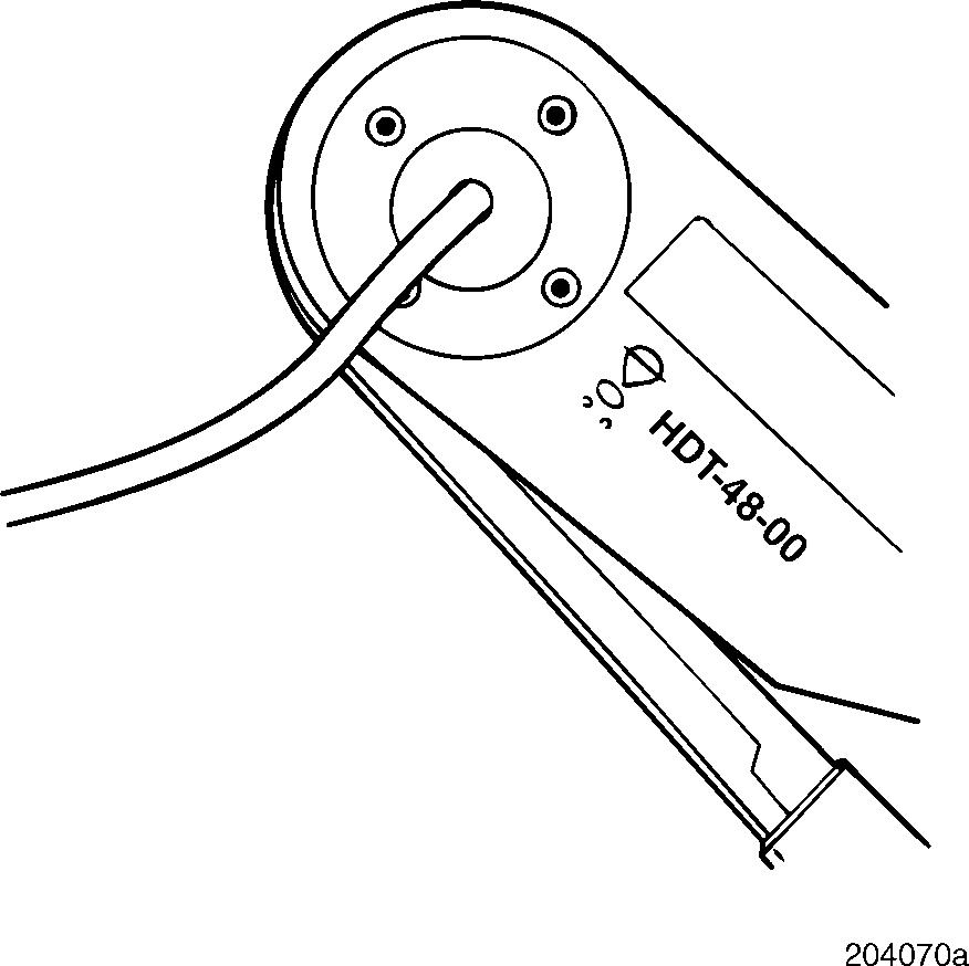
To replace a contact on a wire, use the Deutsch hand crimp tool, part No. HDT-48-00.
1.Strip approximately 1/4 inch of insulation from the wire.
Page 221
Repair And Adjustment Procedures
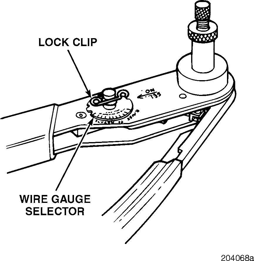
2.Remove the lock clip, raise the wire gauge selector and rotate the knob to the number matching the gauge wire you are using. Then lower selector and insert lock clip.
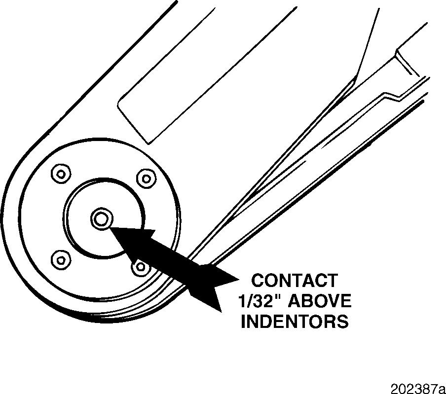
3.Position the contact so that the crimp barrel is 1/32 inch above the 4 intenders. It may be necessary to adjust the hand crimp tool in order to position the crimp barrel correctly.
5.Place the stripped end of the wire in the crimp barrel and fully depress the tool handles.
6.Release the handles and remove the crimped terminal.
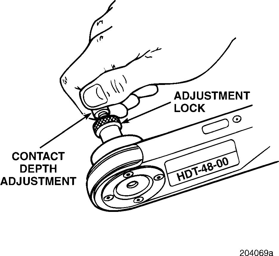
4.Loosen the adjustment lock and turn the contact depth adjustment to obtain 1/32 inch. Then tighten the adjustment lock.
Repair And Adjustment Procedures
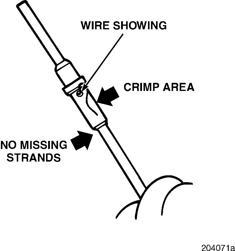
7.Inspect the terminal for proper crimping: r All strands should be in the crimp barrel. r The wire should be visible in the inspection hole.
TERMINAL REMOVAL
To remove the terminals from these connectors, use the following procedure:
1.Grasp the connector body firmly and pull the terminal toward the rear of the connector (as far as possible).
2.Locate the terminal lock tab in the connector.
3.Insert tool No. J 35689-A straight into the slot at the front (mating end) of the connector to release the locking tab for the terminal to be removed (see illustration).
4.After releasing the tab, push the wire from the rear through the front of the connector.
TERMINAL INSTALLATION
After repairing or replacing the terminal, reinstall as follows:
1.Pull the wire from the rear until the terminal slides into the connector body and locks in place.
2.Gently push the wire toward the front of the connector to be sure the terminal is locked in place.
Page 223
Repair And Adjustment Procedures
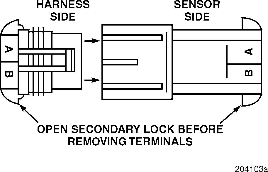
MPH, RPM/TDC, Throttle Position, TEM Sensors and Connectors and Bulkhead Connector
TERMINAL REMOVAL
To remove the terminals from these two-part connectors, use the following procedure:
Removal is the same for both halves of the connector.
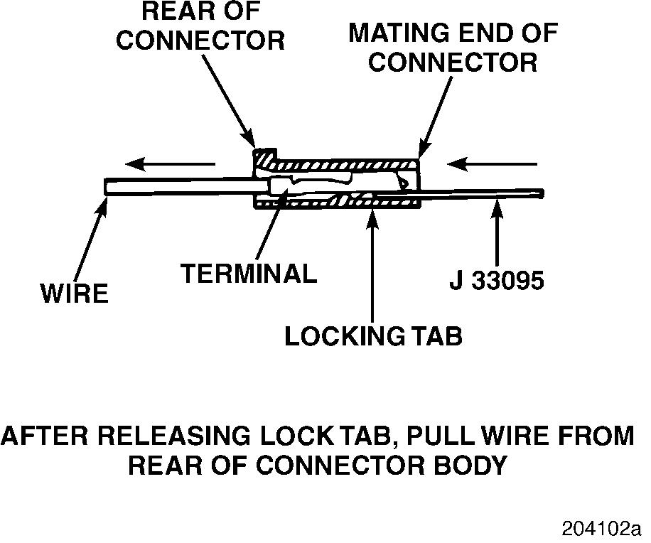
1.Grasp the connector body firmly and push the terminal as far forward in the connector as possible.
2.Locate the terminal lock tab in the connector.
3.Insert tool No. J 33095 straight into the slot at the front (mating end) of the connector to release the locking tab for the terminal to be removed (see illustration).
TERMINAL INSTALLATION
After repairing or replacing the terminal, reinstall as follows:
1.Push the terminal into the connector body from the rear until it locks in place.
2.Gently pull on the wire to ensure that the terminal is locked in the connector.
On some connectors, there is a secondary lock which must be opened before the terminals can be removed.