
2 minute read
DIAGNOSTIC CODE 5-2


Checking for a defective sensor
1.Replace the TPS.
2.Turn the ignition key to the ON position.
If code 5-2 is present, reinstall the original TPS and replace the V-MAC II module.
If code 5-2 is not present, replacing the TPS has solved the problem.
Test 34
Checking for an open in the V-MAC II module or connector
1.Reconnect the TPS and the J1B connector.
2.Turn the ignition key to the ON position.
If code 5-2 is still present, replace the V-MAC II module. Retest to be sure the problem has been corrected.
If code 5-2 is not present, the problem has been corrected. Recheck all connectors to ensure proper connections.
DIAGNOSTIC CODE 5-3
DIAGNOSTIC BLINK CODE 5-3
FUEL CONTROL ACTUATOR TESTS
When performing electrical tests, it is important to wiggle wires and connectors to identify intermittent connection problems.
Test 1
Checking for an open in the actuator circuit
1.Turn the ignition key to the OFF position.
2.Disconnect the engine harness from the injection pump connector on the pump end of the harness.
3.Measure the resistance between Deutsch pins B and G, on the injection pump connector.
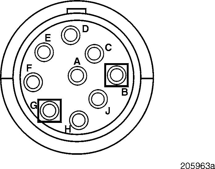
If the resistance is between 0.5 and 1.5 ohms, proceed to Test 2.
If the resistance is not between 0.5 and 1.5 ohms, continue with the next step.
4.Visually inspect the pins and crimps in the injection pump connector, at the pump end of the harness, for the cause of the open.
If there is a repairable condition, repair. Retest to be sure the problem has been corrected.
If there is not a repairable condition, send the pump to a certified pump shop for repair of the pump or integral jumper harness. Then retest to be sure the problem has been corrected.
Test 2
Checking for an open in the harness
CODE 5-3
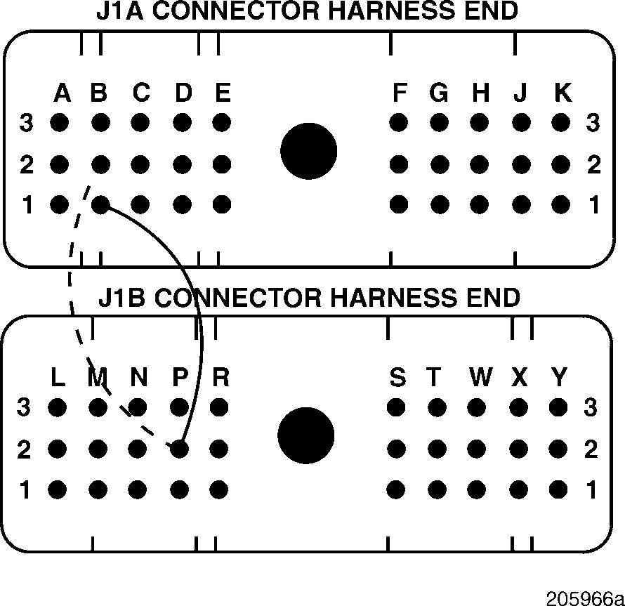
1.Disconnect the J1A and J1B connectors from the V-MAC II module.
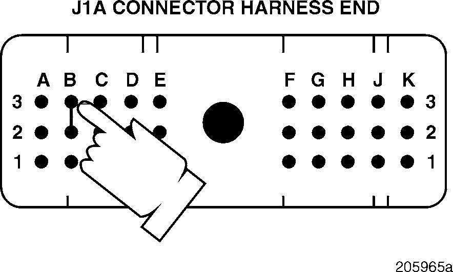
2.Connect a jumper between J1A connector pins A2 and B1.
3.Check for continuity between Deutsch pins G and B, on the pump end of the harness.
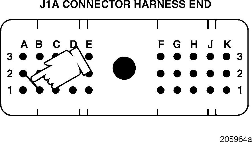
4.Connect the jumper between J1A connector pins B2 and B3.
5.Check for continuity between Deutsch pins G and B, on the pump end of the harness. If there is continuity in all tests, proceed to Test 4.
If there is no continuity in any of the tests, proceed to Test 5.
Test 4
DIAGNOSTIC CODE 5-3
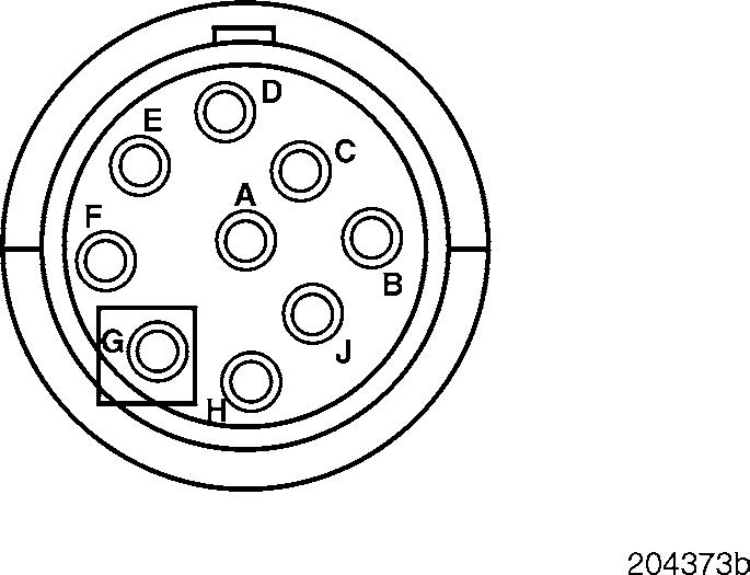
Checking for an open on the pump end of the harness
Test 5
Checking for an open in the actuator PLUS (+) line on the module end of the harness
1.Remove the jumpers between J1A connector pins A2 and B1 and J1A connector pins B2 and B3.
2.Reconnect the pump end of the harness to the injection pump connector.
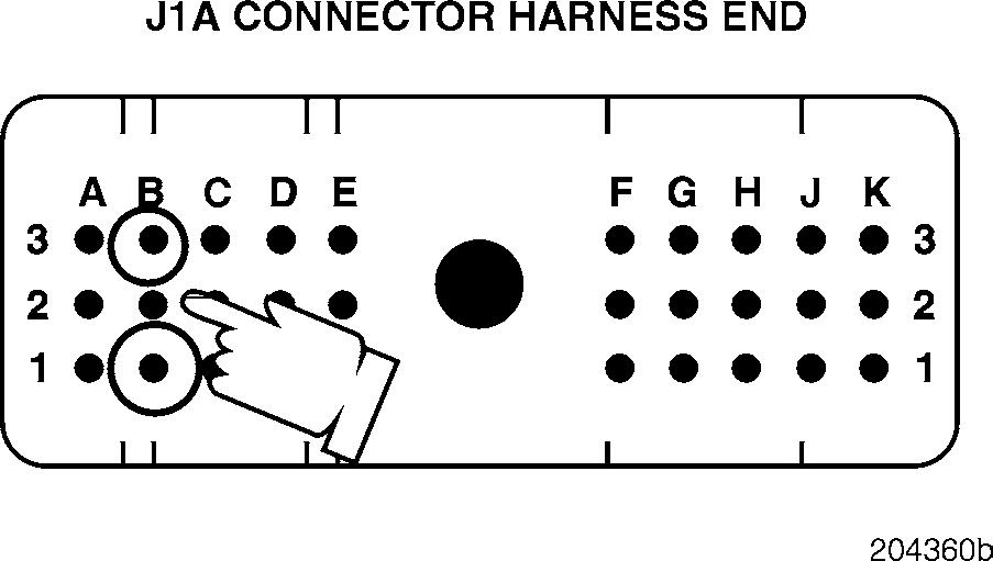
3.Measure the resistance between J1A connector pins B1 (the fuel rack actuator PLUS [+] line) and B3 (the fuel rack actuator MINUS [ ] line).
If the resistance is between 0.5 and 1.5 ohms, proceed to Test 8.
If the resistance is not between 0.5 and 1.5 ohms, the actuator PLUS [+] or MINUS [ ] lines are open in the injection pump connector or the pump end of the harness. Repair the connector. Retest to be sure the problem has been corrected.


